StereoCAD — User Guide
StereoCAD is stereo restitution in CAD on oriented photogrammetric images: you look at the model in stereo, place the floating mark on the ground and draw in 3D. It is the new StereoCAD, the successor of StereoCAD64, built on the same platform as StereoCloud3D.
What is new in 1.4.13 — image orientation
- Ground control points lead the block. With measured points the block follows them, and the residuals on the points go down. Without points the reference stays the GNSS. In Image orientation the box “Ground points rule the block” starts checked.
- Full resolution. Tie points are found on the whole images, without reducing them; enormous images are worked in tiles. Orientation takes longer. A reduction can still be asked for in Advanced.
- Strongly distorting lenses. Image pairs are verified taking the lens into account, so the corners of the photos enter the computation too. On DJI drones the start is the factory calibration written in the images.
- Images not oriented. From the result, “Exclude the images not oriented and run again” leaves them out of the new orientation; “Readmit them” brings them back.
- Ground control points. A point can be disabled and enabled again, or deleted with all its measurements.
- Coordinates. A new project no longer inherits the files of the previous one, and a coordinate file with no measurements no longer comes back on its own to block Start.
- Clear results. Every result starts from what succeeded; at the end comes what to address, with what to do.
What is new in 1.4.12 — drone flights with nadir and oblique images
- Navigation surface on drone images. On low flights with smaller images the surface could come out empty and still count as ready: it is now measured, and an empty surface already saved is made again when the project opens.
- More reliable ground control points. With strongly distorting lenses the program could propose images that do not really see the point: it no longer does. From Pix4D projects the ground control points come in by themselves, with their measurements on the images (8.3).
- Flights on the diagonal. With the stereo on, the view turned like the stereo shows the mosaic and, from near, the real photograph; before, without a cloud, it stayed empty. Visit point, the Overview, continuous roaming and the + and − keys work there too.
- Show: Map and Rotation. Map switches the mosaic and the navigation photographs on and off. Rotation, on flights on the diagonal, brings back the view from above turned like the stereo, keeping the scale and the mark's position.
- A more faithful map. The mosaic and the photographs use the nadir images only, laid on a smoothed surface: straight edges stay straight. The mark's elevation does not change.
- Dense cloud. In “Terrain and buildings” obliques stay out at 45 degrees too, with a cleaner result and shorter times; the count and the time estimate say so.
- First pair and summary. With nadir and oblique images the first pair is a nadir one, and the overlap is computed on the nadir images.
- Auto Z button. On the Stereo bar, it switches the continuous automatic elevation on and off: the ring around the mark is green when the match is good, red when it is not.
- Rubber band on the mark. While drawing in stereo the line ends exactly on the centre of the mark, not on the plan's pixel.
- Esc in the turned view. It holds and resumes the stereo on flights on the diagonal too, and the mark stays where you were working when the hand goes to the menus.
- No cloud import. Point clouds are no longer imported: work on clouds belongs to StereoCloud3D. A DSM can still be imported, and a cloud imported earlier stays visible.
New in 1.4.11 — a large stereo, a plan you can read from near
- No more tiny model. With the plan on the whole block the stereo started very small in the middle of the screen: now the two images fill the stereo screen. The wheel forward enlarges from the first notch; the wheel back no longer enlarges the plan by mistake.
- The keypad's + and −. They zoom the stereo in and out by two at a time, also when looking only into the stereo.
- The real photograph under the plan. From near the plan shows the photograph, as sharp as the stereo, instead of the blurred mosaic and the cloud's scattered points (chapter 11).
- Visit point. Ctrl+G takes the point where you are and the mark stays until you press Go or Enter, so the mouse can reach the window.
- Ground control points. The list shows X, Y, Z and the offset between orientation and survey, on an imported orientation too. Files with a decimal comma or North before East now read correctly (8.3).
- A block in several folders. Nadir and obliques: the program finds every folder and lists them with a tick; with BINGO each folder may have its camera. Nadir and oblique images are not paired in the stereo.
- DTM for CAD. From the dense cloud panel the DTM goes out as DXF, 3D faces or points, and as GeoTIFF (9.6).
- Kensington trackball. The item carries its name and is in the Stereo menu too (12.2).
What's new in 1.4.10 — no more getting lost on the model
- Navigation surface always ready. When a project opens, one made earlier too, the program waits with a progress bar until the navigation surface and its photographs are ready: no more black plan. The same before the stereo starts.
- An Overview that answers. A click takes the plan and the stereo there, with the stereo off too; held down, they follow the mouse. The map shows the photographs and the ground control points. Back on the plan, the mark stays where it is (11.2.1).
- Visit point (Ctrl+G). Type the coordinates, or choose a ground control point from the list, and the plan and the stereo go there at 1:1 (11.2.2).
- Continuous roaming (F10). The mouse has no edges, as in StereoCAD64: you can look only into the stereo. Useful messages appear inside the stereo.
What's new in 1.4.9 — right heights even when GNSS and ground control points disagree
- GNSS weights checked against the ground control points. When after the triangulation the control points are off by more than twice their accuracy, the GNSS of the images was weighed too much: positions that agree with each other but not with the ground, which bend the block and get the heights wrong away from the points. The program widens the GNSS accuracy by itself and runs the final adjustment again, with no box to tick; the report says so. On a flight of 224 images with 44 check points the height error went from 9.1 to 3.3 cm; with a good GNSS nothing changes (8.2).
- Triangulation choices. Image orientation reopens with the choices of the last triangulation, also when its block was not imported: it used to take those of the active orientation, and a box turned off could come back on.
- Images without tie points. An image left without tie points after the adjustment is no longer written as oriented: it could make the import refuse the whole block. The report names them.
What's new in 1.4.8 — what the ground control points are worth, images left out recovered
- Cross-validation of the ground points. Each control point is left out in turn and measured by the block adjusted without it: the real error where there are no points. The result window shows it beside the residuals of the control and check points (8.2).
- Ground points rule the block. Optional, as other programs do: the points weigh 5 mm and the GNSS of the images 10 m, the residuals on the points go near zero and the cross-validation gives the real error. It helps when GNSS and points disagree; run both and keep the one with the lower cross-validation.
- Deep recovery of the images left out. When the triangulation leaves out images with GNSS, the result says so with the extra time and offers Again with the deep recovery: the images are searched again with the calibrated camera.
- Ground control points after Import images. With the ground control points window open, importing a block with fewer images could close the program: corrected.
- Texts. The Code classes button and window, the row of the recovered images and a menu tooltip showed an internal name instead of the text: corrected in every language.
What's new in 1.4.7 — stable 3D view with the dense cloud, clearer stereo
- Dense cloud in the 3D view. With large clouds the program could close while it loaded a new piece of the cloud: corrected.
- Stereo bar. The stereo bar sits on a blue band labelled Stereo, so it stands out from the other bars (11).
- 3D window closed. If the 3D window is closed from the Windows taskbar or with Alt+F4, stereo turns off and a message says why, as in StereoCloud3D.
- StereoCloud3D 5.16.1 engine. The window no longer waits for the disk while it reads the cloud.
What's new in 1.4.6 — resizable 3D window and a tidier Stereo menu, safer triangulation, mixed heights detected
- Resizable 3D window. Stereo › Stereo monitor › Resizable 3D window, off by default: with quad-buffer stereo the 3D window and the main window become normal windows, to move and resize like the others. Without quad-buffer the 3D window stays full screen (11.1).
- Stereo menu in order. The first line says whether stereo is on and on which monitor, then the everyday commands; layouts and checks are in two submenus, Stereo monitor and Checks and diagnostics, with the same scheme as StereoCloud3D (11).
- Triangulation at full resolution. The program works together only the photos that fit in the free memory, and a photo that still does not fit is lost alone, without closing the program (8.2).
- GNSS heights of the images. In Image orientation the choice above sea level / on the ellipsoid is there also when the positions come from the EXIF; with ground points it is required. On the ellipsoid the heights are brought to sea level with the geoid (8.2).
- Report. When the estimated focal length moves more than 10% from the EXIF one, the report says Problem and explains the usual cause: GNSS heights on the ellipsoid and ground points above sea level (8.5).
- Plan never black. Without the photo mosaic the plan shows the photo footprints and frames them, and a line at the bottom says what is missing (photos not found, surface in preparation, height not measurable).
- StereoAtlas. The georeferencing computed in StereoAtlas is proposed and applied as a new orientation; Ground points › For StereoAtlas writes the measured points for it.
- Corrections. No more crash closing a project with the drawing open in the plan and in the 3D view; the log of a session still open is no longer erased at restart; the splash shows the copyright under the version.
- CAD engine aligned with StereoCloud3D 5.16.0: the 3-point rectangle stays active after each rectangle until Esc or Enter.
What's new in 1.4.5 — photos left out of the triangulation recovered, ground points easier to place, StereoCAD64 projects from the File menu
- Photos recovered in the triangulation. Photos left out by the first orientation are brought back before the adjustment: a detached group of photos linked among themselves is oriented on its own GNSS, a single photo starts from the ground points read (at least 4) or from the GNSS, and the tie points are searched only where they must fall. A recovered photo that ends far from its GNSS is refused instead of entering in the wrong place. The Triangulate window has a new Images recovered line and the report says how many came back and how (8).
- Ground points. In the point window you move the crop by dragging with the right or middle button, beyond the zoom; the point name is written next to its mark, also for the other points nearby, without overlapping (8.3).
- StereoCAD64 projects. File › Open StereoCAD64 project (.scad)… and the same button in the welcome screen: images, orientations and drawing of the old project open as a new project; the original is not changed (20.1).
- Import: photos and previews with the same name. When small previews have the same names as the photos, the import takes the photos at the camera size and says clearly when a folder holds only previews or reduced copies.
- Code tables in text format. Load library also shows the code tables in text (.txt), such as the RFI one (14.1); classes of codes with Code classes….
- Properties of a drawn line. In the 3D view the right button on a selection gives the entity menu; Modify › Entity properties and Vertices as well. Elevation wheel or trackball ball and mouse together without jerks.
- CAD engine aligned with StereoCloud3D 5.15.0.
What's new in 1.4.4 — drawing driven by the stereo, ECW images, Metashape XML in degrees, support
- Drawing follows the stereo, with no edge. During a drawing command the mouse moves the mark and the model slides under it, with plan and stereo in step (the default): at the edge there is no more waiting. The same in the 3D view: the view follows the mark and the click takes its point. F8 switches it off (11.6).
- Elevation without jerks. The elevation wheel no longer redraws the plan at every notch: the plan adapts once, when the elevation stops. Going towards the menus, the mark goes back where the hand stood still.
- ECW images. At the import and in the triangulation the ECW images are converted once into TIFF in the project's
immagini_ecwfolder, with a progress bar; a new import reuses them. - Metashape XML in degrees. A Metashape project in WGS84 (usual for drone flights) goes by itself into the StereoCAD project's system, or into the UTM zone, with the markers, and heights brought above the sea. Cameras grouped in folders are read too.
- Share with support. Help › Share with support… builds a zip with a picture of the window, the log, a description of the computer and your comment, to attach to an e-mail. After a crash StereoCAD asks whether to send the report to MENCI Engineering (19.1).
- Stereo AI: Copy. "Copy" under every answer and "Copy all" at the top.
- Side photos and pylons. Photos without EXIF are read, the stereo of side photos is shown on the plane facing the view, the plan turns with the stereo on blocks flown off east-west.
- Triangulation and dense cloud. Photos that slid along the strip go back onto the GNSS; under the water of marshes the dense cloud no longer leaves a second layer of points.
- Ground point reading up to 4:1.
What is new in 1.4.3 — plan, Overview and stereo always in step, 1:1 zoom, flat water in the dense cloud
- One rule for the pair. The plan, the Overview and the automatic change choose the pair the same way: the pair no longer jumps back and forth at the same point.
- The mark never lags behind. Where the stereo cannot go (pair locked, no pair sees the point) the mark stops on the edge of the model and the status bar says why. With the mouse off the plan, the CAD crosshair follows the mark and the plan keeps it in sight.
- The Overview drives the stereo. Rest the mouse on the map for a moment (a ring fills up and the pair that will be shown is outlined): then the mark follows the mouse and the pair changes by itself. A mouse crossing the map without stopping moves nothing. The map shows the plan's rectangle and keeps the mark in sight.
- 1:1 zoom. Ctrl+1, a click on "Stereo 1:1" in the status bar or Stereo > View. The wheel goes by steps that always pass through 1:1, and the zoom chosen stays when the pair or the elevation changes.
- Free zone off by default. The plan no longer scrolls by itself; switch it on with Scroll.
- A sparse navigation surface, with the photos. When the project opens it measures in a few seconds a light surface (40,000 points at most, on reduced photos) and lays a mosaic of the photos on it: in the plan it is a photographic background (the Orthophoto layer, under real orthophotos), in the stereo on the surface it colours the ground. The dense cloud no longer starts by itself: it is made when needed, like the DSM.
- Water and reflections. Areas the photos cannot measure, with a level shore and the colour of water, become flat water at the shore's level; measurements below that level (reflections) are dropped. Roofs, shadows and bright fields stay as they are.
- Water in the dense cloud and the DSM. On calm water (marshes, ponds, canals) the measurements sank by metres or jumped up. Now the dense cloud recognises water from the uniform image and the scattered measurements, takes its level from the part measured well and makes it flat: in the DSM at that level, in the cloud with points marked as water (class 9, synthetic) in place of the wrong ones. Shores, reeds, roads on embankments and squares stay as measured. On the plan the Rebuilt roofs mask shows water in blue; the Rebuild the roofs option turns it off. With the Recognise water with Stereo AI option (under Rebuild the roofs), before the dense cloud Stereo AI looks at a reduced mosaic of the photos and says where there is water: it is made flat only there, and nothing in a town. Ticking it is the consent to send that picture (one, about 1500 pixels; free, once per project). Without the option the geometry alone decides, with a stricter rule.
What is new in 1.4.2 — free zone of the mark you can size, graphics card in the log
- Free zone size. Stereo > View > Free zone size sets how much of the plan the mouse moves the mark in freely, 30% to 90% (50% at the start): larger, the plan scrolls only near its edges. It is saved in the project; the free zone still switches off with the Scroll button (11.4).
- Graphics card in the log. At start the log says which graphics card draws the program and, when it is the integrated one of the processor, what to do to use the dedicated card.
What is new in 1.4.1 — orientations from your own table, ALOS PRISM, delivery samples, contour labels fixed
- Camera typed by hand. In the BINGO / OPK import, without a
.bcccamera file, type the focal length and the pixel from the camera's data sheet: the image size is read from the images, the principal point is at the centre, no distortion (7.1). - Stereo AI writes the orientation file. Orientations in a table of your own (columns in another order, decimal comma, gon or radians): Stereo AI reads it, shows a preview and, after your yes, writes the file into the project and fills the Import window. The program copies the numbers (7.1).
- ALOS PRISM without RPC. ALOS PRISM level 1B1 views (JAXA's CEOS format) are imported from their rigorous model: orbit, attitude and the geometry of the detector strips. The four strips of each view become one image, straightened and written in the project's folder (7.1).
- Deliveries with orbit and attitude only. A delivery StereoCAD does not read yet because it has only orbit and attitude (SPOT 1–5, for example) becomes, with your consent, a sample for MENCI Engineering, who write its reader: only the metadata files leave, never the images (7.3).
- Contour labels. The labels of contour lines no longer close the program.
New in 1.4.0 — free Stereo AI, satellites, accuracy, license agreement
- License agreement at the first activation. The first time a key is activated, StereoCAD shows the end-user license agreement (EULA) in force: you read it, accept it with your name and organization, and it is not asked again. It can be read again from (5.2).
- Read only. If the maintenance fee is not renewed, StereoCAD does not close: for 12 months it opens and shows your projects, but does not change, save, export or print them. The Renew... button in the menu bar opens a message to MENCI Engineering (5.4).
- Ask Stereo AI is free: its answers do not use AI credits. The main windows (Import, New project, orientation, Dense cloud, Reference and accuracy, Sensor library) and the Stereo menu have their own Ask Stereo AI button, which opens the assistant with a question about that window already written and not sent; the question field wraps and shows the whole question (10.5).
- Stereo AI: what this project allows. When a project opens, Stereo AI looks at the data in its folder and proposes the work it allows, each with the reason and the products you get; a click opens the command (6.7).
- Satellite sensor library. A folder you choose, untouched by updates, where StereoCAD keeps what it learns about the satellites of your data. When a delivery has a format StereoCAD does not read, Stereo AI learns it from the delivery's documents, or searches the web for the supplier's public documentation; the description is checked on the scene before it is used. MENCI Engineering bears the cost (7.3).
- Rigorous model of Pléiades, SPOT 6/7 and SpaceEye-T. A scene without its RPC is read from the orbit, attitude and viewing directions of the delivery (DIMAP v2). A Pléiades product delivered in several tiles opens as one scene, also from a USB disk (7.1).
- Reference and accuracy report. A laser survey or another program's DSM is imported as a reference, shown in the plan view and compared with the project's DSMs: spread, systematic offset, plan shift, difference map and a report for the client (9.8).
- Satellite pairs with a stereo base. Each scene is paired with the one that gives a good depth (base to height ratio close to 0.6), not with the nearest: two views of the same pass make no stereo (11.3).
- A tidy first start. At the first start, also on 1920×1080 and 1366×768 screens, toolbars and windows do not cover buttons, the plan view or the right column, and stay on the screen.
- Languages. The license status, activation refusals and license messages are in the interface language; the Stereo AI window also in French, German and Spanish.
New in 1.3.1 — working in stereo in the map's system
- The old map on the ground in stereo. After an old map has been analysed, Work in the map's system shows the old map, as it is in the drawing, on the ground in stereo; the cursor, the coordinates and new points are in the map's system, so the update joins the old map without steps. Images and orientations do not change: the parallax stays zero (15.4.1).
New in 1.3.0 — updating an existing map
- File › Update an existing map. An old 3D map (DWG or DXF) is measured on the new survey of the project, the causes of the differences are found (geoid, tilt, height scale, plan shift, generalisation of the contours) and a report in three parts is written for the client: study, diagnosis, solution with the predicted result, and why the differences do not go to zero. The map is then corrected, or a new drawing is brought into the map's system, and the prediction is checked. Only coordinates change: the stereo is untouched (15.4).
New in 1.2.0 — regularized surfaces, satellite pairs, Portuguese
- Regularized surfaces. From satellite images and from aerial images of 8 cm or more the DSM is made of planes with sharp steps at the walls, and the dense cloud lies on the surfaces without the “fog” of loose points. Automatic; Always / Never in the dense cloud window (9.1).
- Satellite stereo pairs (first version). A pair of satellite images with their RPC is recognised by New project, seen in stereo and measured with the cursor; the elevation step moves the mark along the line of sight. Dense cloud and DSM go through the RPC, with the pairs aligned in height before they are merged. The orthophoto is not available yet on satellite blocks.
- The Show bar of the plan shows only what can be shown: in amber what the project could make but has not made yet (a click opens the window that makes it), hidden what cannot be made (10.2).
- Brazilian Portuguese for the interface, the orientation report and the setup (10.4).
- License activation: one Enter sends one request; keys and clicks pressed while waiting for the server are dropped.
New in 1.1.2 — the trackball for the elevation
- Kensington Expert Mouse and other trackballs. Chosen as the photogrammetric mouse, a trackball becomes Trackball for the elevation by itself: the ball moves only the elevation, the normal mouse the plan. The ball now changes the elevation also over the plan and with the stereo window in front, and with the stereo off it raises and lowers the plan cursor's elevation (12.3).
- Faster tie points on large photographs. The aerial triangulation reads 2 GB photographs from their pyramids, and the progress bar says which photograph it is reading.
New in 1.1.1 — the right heights for flights with GNSS/IMU
- Heights on the ellipsoid or above the sea. For a BINGO / OPK file (Import and New project) and for the GNSS file of the orientation you choose where the heights are measured from. With On the ellipsoid (GNSS) StereoCAD brings them above the sea with the EGM2008 geoid, so that the project matches the maps and the drawings: in Italy the two differ by 40-50 m (7, 8).
- Focal length from the certificate. Without control points a calibrated camera
(
.bcc) keeps the focal length and the principal point of its certificate: with the GNSS alone the focal length trades with the height of the ground. Freed, and moved away from the certificate, the verdict reports it as a problem.
New in 1.1.0 — Stereo AI, the assistant inside the program
- Ask Stereo AI, the green button in the menu bar: describe what you want to get on your dataset and Stereo AI answers with the steps, opens and fills the right window, reads the project state and the log. How to use it in its window suggests example questions (10.5).
- AI credits always visible in the status bar, and their top-up (10.5).
- The terrain (DTM) of the contour lines saved next to the DSM and shown in the plan; contour lines on sparse clouds too; the plan picks what to show with Show (10.2).
- Progress bars that never stand still (ground filter, aerial triangulation, dense cloud); a much faster ground filter on large blocks.
- Stereo systems described by their working principle; a splash at start-up and with producer and author.
1. Introduction
What StereoCAD does
- Opens oriented photogrammetric datasets: Metashape, Pix4D, COLMAP / APS3d, BINGO and OPK, OPALS, Z-Map, and the projects and formats of StereoCAD64 (chapter 7).
- Orients images itself: aerial triangulation and bundle adjustment from images with GNSS and, optionally, ground control points, with an adjustment report (chapter 8).
- Generates the dense point cloud, the DSM and the orthophoto from the oriented images, on CPU or NVIDIA GPU, and imports the DSMs of other programs (chapter 9).
- Shows the stereo model on passive, active-shutter and beam-splitter stereo displays, with roaming between pairs, floating mark, fine pointing and automatic elevation (chapter 11).
- Draws in 3D with a full CAD, feature codes and attributes, and exports DXF, DWG, Shapefile and GeoPackage (chapters 13–15).
What StereoCAD is not: a point-cloud processing program. It has no classification, no automatic extraction of lines or roofs, no sections or volumes: those belong to StereoCloud3D. The dense cloud and the DSM are there to view the model and to give the cursor its elevation.
2. Key concepts
- Project
- A folder with a
manifest.json, the dataset, its orientations, the products and the drawing (6.4). StereoCAD and StereoCloud3D refuse each other's projects. - Orientation (photogrammetric block)
- Cameras (focal length, principal point, pixel size, lens distortion) and, for each image, the projection centre and the rotation. Each import or triangulation creates a new orientation in the project, which becomes the active one; the previous ones are kept.
- One internal model
- Every format is converted once, at import, to the same model: undistorted image, ideal camera, centre and rotation matrix. Angle conventions (omega-phi-kappa, order, units) are declared per format and converted in the importer; the distortion is removed once, in the stereo images, never at run time.
- Stereo pair and navigation plane
- Two overlapping images seen one per eye. StereoCAD resamples them on the horizontal plane at the elevation of the mark, so moving from one pair to the next does not jump.
- Floating mark
- The 3D cursor: its X and Y follow the mouse, its Z changes with Shift+wheel, the devices or the automatic elevation. A vertex drawn in stereo takes the mark's 3D point.
- World coordinates
- Everything is in the project's reference system, in double precision. The drawing and the exports are in world coordinates.
- Grid and true metres
- In a projected system (UTM, Gauss-Boaga...) horizontal distances on the grid are k times the true ones (UTM about 0.9996), heights are not. For blocks adjusted in true metres (StereoCAD's own triangulation, Metashape) StereoCAD works internally in a local metric frame and applies the Earth's curvature, so stereo heights stay correct far from the nadir; inputs and outputs remain world coordinates. Blocks adjusted on the grid (Pix4D, generic OPK, Z-Map) are used as StereoCAD64 used them.
3. System requirements
| Item | Requirement |
|---|---|
| Operating system | Windows, 64-bit (x64). |
| Graphics | OpenGL 3.3 core profile. Without it the window does not open. |
| Stereo display (optional) | Two extended displays for SBS / Top-Bottom, three for a two-monitor beam-splitter mirror (passive polarisation), a 120 Hz panel with active shutter glasses and an infrared emitter for frame-sequential stereo (11.1). |
| Dense matching on GPU (optional) | NVIDIA, Turing or newer (GTX 16 / RTX 20 and later), at least 1.5 GB of graphics memory, a current driver. Without it the CPU does the same work, more slowly. |
| Internet | Required: the license is checked online at start-up and while the program runs. Licenses enabled for offline use (on request) need it only from time to time, and a computer that is never online can use a license file (5.1). |
| Disk | The stereo images of distorted cameras are resampled into tiled copies that can take as much space as the originals. Dense matching is much faster on a local SSD than on a USB or network disk. |
| Devices (optional) | 3Dconnexion SpaceMouse, Stealth V / Stealth Z, a trackball (chapter 12). |
4. Installation
- Run
StereoCAD-Setup-1.2.0.exeas an administrator. The setup speaks English, Italian, French, German and Spanish. - Choose the folder (default
C:\Program Files\StereoCAD). A temporary folder is refused, because Windows empties those folders. - Optionally tick the desktop icon, then finish; the last page can start StereoCAD.
The setup refuses to run while StereoCAD or one of its tools is running: close them first. StereoCAD installs beside StereoCloud3D without touching it: separate program, separate settings, separate license.
Installed: StereoCAD.exe; the engines it starts as processes (at_builder.exe,
dense_builder.exe, octree_builder.exe); the CAD converters
(carto_dxf_to_vec.exe, sc3d_dwg.exe); the CAD fonts and linetypes; the
feature code libraries (codes\); the PROJ and GDAL data; this guide
(manual\, also in the Start menu as StereoCAD User Guide); the third-party
notices.
To uninstall: Windows Settings › Apps, or Uninstall StereoCAD in the Start menu.
Your projects and %APPDATA%\StereoCAD are not removed.
5. License activation
StereoCAD needs an active online license. Keys have the form SCAD-…; a
StereoCloud3D key does not activate StereoCAD, and the reverse.
- At start-up the window StereoCAD – Activation shows the Device fingerprint (16 characters) and the field License key.
- Enter the key and press Activate. The last accepted key is remembered for this Windows user (encrypted) and proposed at the next start.
- Quit closes the program.
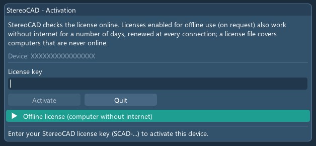
While StereoCAD runs it checks the license every minute. If the server stops answering, the title bar counts down (LICENSE: connection lost – closing in N s) for five minutes: save your work as soon as the connection returns. A license that is revoked or suspended, or that expires after the 12 months of read-only use (5.4), closes the program with a message.
5.1 Working without internet
Offline use is off by default and enabled license by license on request: ask your license administrator. On such a license, every answer of the license server gives this computer a signed offline lease: StereoCAD keeps working without the server for the days the license allows (usually 14, never beyond the license expiry), and every connection renews them. While offline the title bar shows LICENSE: offline, N days left, and the license status shows the days left and the end date. StereoCAD also starts without internet, on the lease of the last connection.
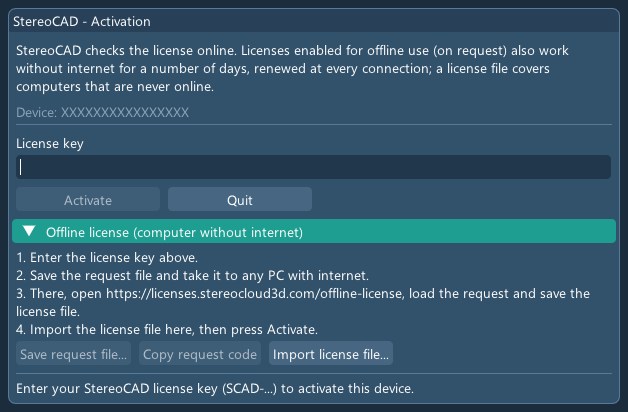
Computers that are never online. In the activation window open Offline license
(computer without internet): enter the key, Save request file... (a .sc3dreq
file; Copy request code gives the same request as one line of text), take it to any PC with
internet, open https://licenses.stereocloud3d.com/offline-license there, load the request
and save the .sc3dlic license file. Back on the offline computer, Import license
file..., then Activate.
Lease and license file are valid for this computer and this version of StereoCAD only: after an update the lease renews at the first connection, while a license file must be requested again. A StereoCloud3D license file is refused. Times are UTC, so a time-zone change does not matter; a clock set back by more than about a day stops the offline license until it is correct. A revoked or suspended license stops at the first connection, and its lease and license file are deleted.
shows status, license type, expiry, contract (Commercial, Trial, Educational, Public administration), devices activated, this device, server and connection, the version of the license agreement accepted and, in read-only use, until when it lasts. Read the license agreement (EULA) opens its text. Deactivate this device... frees the activation for another computer; it closes StereoCAD and is disabled while the project has unsaved changes. The whole panel is in the interface language.
5.2 The license agreement (EULA) at the first activation
The first time a key is activated, after Activate StereoCAD shows the window License agreement (EULA) with the text in force, downloaded from the license server in the interface language. To continue:
- read the text;
- tick I have read and accept the license agreement and the box that specifically approves the clauses listed (art. 1341-1342 of the Italian Civil Code);
- fill in Name of the person accepting and Organization;
- press Accept and continue.
The acceptance is recorded on the license server with the name and the organization; it is not asked again at the next starts. Quit closes the program without accepting. If the text does not arrive (no network), the window says so: check the connection and press Retry. The text can be read again at any time from › Read the license agreement (EULA), and it is published at www.stereocad.com/eula/. The same EULA is also accepted on the site's download page.
5.3 License and maintenance contract, AI credits
StereoCAD is bought with the license and maintenance contract: an entry fee covers the first year; from the second year an annual fee renews license and maintenance for another 12 months. There are no perpetual licenses, and the contract does not renew by itself: it renews when the fee is paid. Every paid year includes:
- the updates and new versions of StereoCAD;
- technical support by e-mail at
info@menci.com; - the online license service;
- Ask Stereo AI, which uses no credits (10.5);
- 500 AI credits for the Stereo AI functions that use them, such as Stereo AI: what this project allows (6.7). At the start of every paid year the included credits go back to 500: those not used do not pass to the next year.
Topped-up credits (for now ordered from info@menci.com and paid by bank
transfer: 10.5) are used after the included ones and do not expire while the
contract lasts: at renewal they stay and are added to the year's 500 (for example, 600 topped-up credits
not used become 1,100 after the renewal). A request that fails uses no credits; when the credits run out
only the functions that use them stop, the rest of the program works. The trial license lasts 7 days, has
250 credits and cannot be topped up.
The full text: license and maintenance contract and AI credit terms at www.stereocad.com. Where this guide and those texts differ, those texts prevail.
5.4 Read-only use
If the fee is not paid by the expiry date, or the contract ends, the license goes into read-only use for 12 months. StereoCAD still starts with the same key; the menu bar shows Read only, highlighted, with the Renew... button, and hovering over it says until when it lasts. If the contract ends while StereoCAD is open, the program turns read only at the next license check (within about a minute), without closing, and says so with the message License: read only: from then on changes not saved yet can no longer be saved.
| You can | You cannot |
|---|---|
| Open your projects and look at them: plan view, stereo, images, drawing, clouds, DSMs and reports already made. | Create projects, change the drawing or the project, save, import, export, print, generate clouds, DSMs and contours, update a map; use the Stereo AI functions. |
An operation that is not allowed is refused with the message Read only: this operation is not available, which also appears in the menu bar; the project does not change. The deliverables already produced and delivered remain the client's and can be used without limits.
How to reactivate. Pay the fee for the new year: Renew... opens an e-mail to
info@menci.com. Within 12 months of the expiry the new year's fee is enough, without the years
skipped; after that, the fee increased by 25%, without a new entry fee. Once the payment is recorded the
same key returns to full use: StereoCAD, even while open, notices it at the next license check (within about
a minute) and says so with the message License: active again; there is no need to restart, reinstall
or activate again.
After the 12 months of read-only use without renewal, the license is deactivated.
6. Projects
6.1 Welcome screen
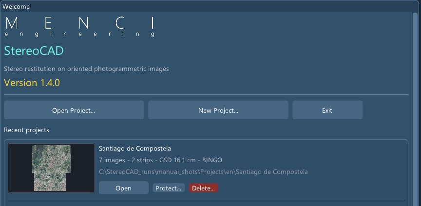
Without an open project StereoCAD shows the Welcome window: Open Project..., New Project..., Exit, and Recent projects. Each card shows a preview of the block, the name, a one-line summary of the dataset, the operator and the path, with:
- Open (or a click on the preview);
- Protect... / Password...: password protection (6.6);
- Delete...: deletes the project folder from disk, permanently, after a confirmation; refused for an open project or a folder that is not a StereoCAD project. A project missing on disk shows Remove from list instead.
6.2 Creating a project
(Ctrl+N):
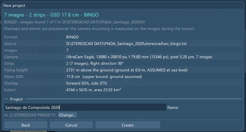
- Where are the photogrammetric data? Choose the dataset folder (Choose folder...) or its files (Choose files...), or drop them on the window. Format, orientation and images are recognised by themselves (up to three folder levels down). Project without dataset (CAD only) makes an empty project.
- The result screen summarises what was found: format, source file, images (found of named), camera, strips and flight direction, flying height, mean GSD, overlaps, extent, reference system, dates. When more datasets are in the folder the best one is chosen and the others are listed.
- Give the project a Name (proposed from the dataset folder) and the parent folder (Change...; the last one used is proposed). Create makes the project and starts the import (7.2).
If the folder holds only images without orientation (at least three JPG or TIFF), the button becomes Orient and create the project: the project is created and the aerial triangulation starts in it (chapter 8). Images in subfolders are taken as one camera per subfolder.
A block in several folders (nadir, oblique1, oblique2): the orientations name the images of all of them and the
program finds them all, up to nine folders. The window lists them with their number of images: untick a folder that is
not part of the block. This holds for BINGO, OPALS, Pix4D, COLMAP and Z-Map folders (several Z-Map folders are one block);
Metashape already found them. With BINGO, a .bcc inside a folder, or with the folder's name in its own, is that
folder's camera; otherwise one camera for all. With a nadir camera the stereo pairs use it: nadir and oblique images are never
paired, and the obliques stay in the block. In File > Import the other folders are added on the row
Other folders of images.
A StereoCAD64 project (.scad) or one of its formats is recognised the same way
(chapter 20).
6.3 Opening, saving, closing
- (Ctrl+O): choose the
project folder (or its
manifest.json). A StereoCAD64 folder with a.scadopens New project already filled in. A project of an earlier StereoCAD layout is converted to the current folders when it is opened (the log lists what moved). - : the last ten.
- (Ctrl+S) saves the drawing, its feature codes and the project state; asks before discarding changes.
6.4 The project folder
<project>\
  manifest.json            name, description, operator, protection, active drawing
  preview.png              the picture of the Welcome card
  dataset\
    attivo.txt             the active orientation
    gcp_points.txt         ground points and their measures (shared by all orientations)
    gcp_measures.txt
    stereo_pairs.json      removed pairs, navigation, tones
    orientamenti\
      <date-time>_<origin>\   one per import or triangulation (origin: metashape, pix4d, colmap,
                                 opk, opals, zmap, scad, a3it, aps, apss, umap, opkbundle, photoscan, at)
        block.json          cameras and orientations
        at\                 triangulation work and report (when StereoCAD oriented it)
        cache\              prepared stereo images (unless another folder was chosen)
        prodotti\<layer>\  dense clouds, DSM, orthophotos, meshes
        cad\drawing.vec     the drawing of this orientation
        cad\drawing.vec.features.json   feature codes and attributes
When a new orientation is made the drawing is copied into it and follows it; the copy of the previous orientation stays where it was. The original images are never modified and stay where they are.
6.5 Project tree
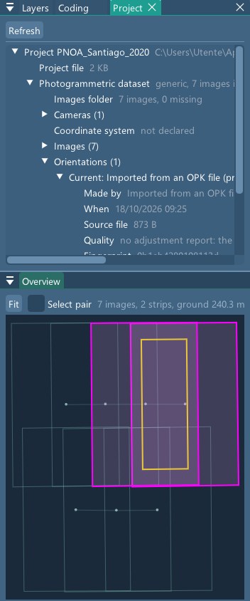
shows what the project is made of and where its files really are: the drawing, the dataset (images found and missing, cameras, reference system, and the metric-frame factor k when it applies), each orientation (made by StereoCAD's triangulation or imported, when, data used, result with sigma0 and RMS, report), the stereo images and the products. Missing files are red. Right click: Show in Explorer, Copy path and, on a previous orientation, Delete this orientation with its products (refused while one of its clouds is shown).
6.6 Project protection
Protect... on the Welcome card sets an operator name and a password; opening the project then asks for a name and the password, and the name becomes the operator of the session. It is a soft protection: it gates opening in StereoCAD, the files are not encrypted. Password... changes or removes it (the current password is needed).
6.7 What this project allows (Stereo AI)
When a project opens, once its block is loaded, the window Stereo AI: what this project allows proposes the work these data allow. Stereo AI receives the facts of the oriented block (images, cameras, where the orientation comes from, coordinate system, control points, satellite scenes, stereo pairs, DSMs, dense cloud) and the list of the project’s folders and file types, with the images folder — never the images. It reopens from .
At the top of the window is the project’s data map: a node per piece of data, left to right as the work flows — Data (images, camera, ground control points), Orientation, Surfaces (navigation surface, point cloud, DSM, orthophoto), Work (stereo, drawing). Green: the data is there; grey: missing; pulsing teal: being made (the navigation surface and cloud make themselves when the project opens); dark grey: optional, or waiting for the data before it. The arrows show what each piece is made from. A missing node carries the step that makes it (for example > Triangulate on the orientation, > Dense cloud on the cloud): a click opens the same command as the menu. The map uses neither Stereo AI nor credits: Stereo AI’s comment is below it.
- It uses the same consent as Ask Stereo AI (10.5); without it the window offers Allow and analyse. Each analysis uses AI credits.
- The answer: two lines on what the folder contains, then the proposals in order of usefulness, each with why, the products worth obtaining and a few questions with the recommended answer marked. Stereo AI chooses only among StereoCAD’s own commands — stereo, aerial triangulation, control points, dense cloud / DSM / orthophoto, contour lines, map update, accuracy report, import of an orientation or of a drawing, GIS export.
- Open runs that command exactly as its menu entry; not available now when the command cannot run yet (for example stereo without an oriented pair).
- Not suitable for these data lists what lacks a fact, with the reason; To do more you would need says which data would open more work.
- The answer is kept in the project (
settings/project_triage.json) and read again for free; when folders or file types change the window says so, and Analyse again asks again.
7. Importing oriented images
The usual way is New project on the dataset folder (6.2). In an open project, adds a new orientation with the format and files chosen by hand.
7.1 Formats
| Format (as in the dialog) | Files | Recognised by itself | Notes |
|---|---|---|---|
| StereoCAD / Z-Map (.int/.est) | Images folder with <image>.int and
.est | yes | The StereoCAD64 sidecars. Rotated scans, perspective homographies and
radial distortion tables in the .int are refused. |
| COLMAP / APS3d (text model) | Model folder (cameras.txt,
images.txt) and images folder | yes | Pinhole, radial and OpenCV cameras; fisheye refused. APS3d model (Menci) (Y and Z of the ground inverted) is recognised by itself. StereoCAD's own triangulation writes this model with its reference system. |
| Pix4D (params folder) | 1_initial\params (calibrated camera parameters,
offset, wkt) and images folder | yes | Used on the grid, as StereoCAD64 did. |
| BINGO / OPK (camera + orientations) | Camera .bcc, or Focal length and
pixel from the camera's data sheet (image size read from the images, principal point at the centre,
no distortion: for images already corrected), exterior orientation file, images folder | yes | ORIA rows, gon, phi-omega-kappa. Rotation of the image
axes: Automatic (found on the images) or 0 / 90 / 180 / 270. A CSV with a header naming the
columns too (id;X;Y;Z;Omega;Phi;Kappa, degrees). Heights of the orientation file, always to
choose: Above the sea (imported as they are) or On the ellipsoid (GNSS), with the EPSG
code of the file's coordinates: the heights are brought above the sea with the EGM2008 geoid and the
EPSG becomes the block's system. A .bcc with distortion terms is refused. |
| Agisoft Metashape (cameras XML) | Cameras XML (or the project's doc.xml),
images folder | yes | Aligned cameras only. Reference system as in the Metashape project or
from a .prj. A Metashape project in degrees (WGS84, usual for drone flights) goes by itself into the
StereoCAD project's system, or into the UTM zone when the project has none yet, with the markers, and heights
brought above the sea (EGM2008); a geographic .prj is refused. Cameras grouped in folders are read
too. |
| OPALS (orientations with interior) | Orientation file with c x0 y0, images
folder, optional tie observations | yes | The export without interior orientation is refused. |
| StereoCAD64 project (.scad) | The .scad | yes | Versions
100–118 and ImageTrack; the .sfi drawing comes with it
(20). |
| 3dCapture / APS3d (.a3it) | The .a3it, optional images folder | yes | Encrypted export: cameras with distortion, orientations, tie points. |
| APS project (.srf) | The .srf (with its .iml) | yes | Bundle\<name>.ori, else .extor with the .int/.est. |
| APSS project (.apss) | The .apss | yes | Needs the
.wcsbro; a project with only the .bro is refused (local coordinates
without offset). |
| uMap project (.ump) | The .ump | yes | Orientations from the
.int/.est written by uMap. |
| OPKBundle project (.bun) | The .bun | yes | Versions 203–208, with their reference system. |
| Satellite images (RPC) | The delivery folder: the scenes with their RPC
(.RPB, _RPC.TXT, .RPC, DIMAP RPC_*.XML, ALOS
RPC-*.txt, RPC inside the GeoTIFF or the NITF, or another text, XML or JSON file with the
usual field names) | yes | The satellite is
recognised from the delivery's metadata (.IMD, DIM_*.XML, .pass,
README and product files in the folder, the one above and a METADATA / DOC
folder beside it), else from the file names: WorldView, Legion, GeoEye, QuickBird, IKONOS, Pléiades,
Pléiades Neo, SPOT, SpaceEye-T, KOMPSAT, EROS, Cartosat, ALOS, ZiYuan-3, GaoFen, SuperView,
Jilin-1, TripleSat and the other optical satellites with stereo. The window says the product level
(sensor geometry or already projected), where the RPC is, whether orbit and attitude are delivered
too and which scenes were taken in the same pass. A single scene, a scene without its image files or
a delivery with orbit and attitude only (SPOT 1–5, ALOS CEOS, ASTER) is recognised but not
imported, with the reason. Every RPC is checked before it is used (it must evaluate, fall on the image
and, when the delivery gives the scene's corners, find them again): an RPC that fails is refused with
the reason. A Pléiades, SPOT 6/7 or SpaceEye-T scene without its RPC_*.XML is read
from the orbit, attitude and viewing directions in its DIM_*.XML (the rigorous model):
StereoCAD computes an equivalent RPC from it, and the import report says how closely it reproduces the
model. A DIMAP product delivered in several tiles (Pléiades, for example) is one scene, from the
DIM_*.XML or from any of its tiles: all the tiles must be there, and a missing one is refused
with the reason. ALOS PRISM level 1B1 views (folders with LED-, SUP- and
IMG- files, JAXA's CEOS format) are read the same way: the four detector strips of each view
become one image, straightened and written in the project's folder. |
| PhotoScan Bundler (bundle.out) | bundle.out, camera .cvc /
.bcc, folder of undistorted images | no: dialog only | Camera n is the n-th
image of the folder in name order. .cvcc, .rdr, .grd are refused. |
ECW images. When the images folder holds the frames as ECW (PNOA deliveries, for example), the import converts them into tiled TIFF by itself, once (about a second a frame), into the project's immagini_ecw folder; from then on StereoCAD works on the TIFFs. The ECW files stay as they are. The conversion uses an ECW reader checked pixel by pixel against the official one. The triangulation (chapter 8) reads ECW too: it converts them into the same folder, and the import after it reuses them. Aerial ECW frames usually carry no EXIF: give the camera (calibration file) and the GNSS positions (a file).
Whatever the format cannot represent is refused with the reason, never approximated. APS, APSS, uMap, OPKBundle and PhotoScan Bundler have so far been verified on test files written by the rules of their writers, not on customer datasets: if you have one, send it to Menci.
Orientations in a table of your own: Stereo AI writes the file. If the
exterior orientations are in a table that is not in the BINGO / OPK form (columns in another order,
decimal comma, gon or radians, titles above, names without extension), choose it anyway in the field
Exterior orientation file, give the images folder and press Ask Stereo AI. Write what you
know: the camera (.bcc file, or focal length and pixel), heights above the sea or on the ellipsoid, the
coordinate system. Stereo AI reads the first lines of the table, finds the columns and shows a preview:
rows read, the first row as it will be written, names found in the images folder (those in ECW are
converted by the import). Nothing is written until you say yes. Then the file goes into the project, in
dataset\tabelle_orientamenti, and the Import window comes back filled when you close
Stereo AI: check it and press Import. The program copies the numbers, not Stereo AI: no value is
retyped. The table can also be given by the path of its file, or pasted in the question when it is short
(the field holds about 4000 characters).
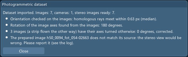
7.2 What the import does
- Reading the dataset. Images whose file is missing are left out (and listed).
- Finding the rotation of the image axes (BINGO with Automatic): the camera mounting is measured on the images; a strip flown the other way can get its own rotation.
- Checking the orientation on the images. Neighbouring pairs are matched and the rays of homologous points must meet. If a decisive pair fails, the import is refused and nothing is saved: the message says by how much the rays miss each other. When no pair has enough texture the import goes on with a note that it could not be checked.
- Preparing the stereo images. Images with lens distortion are resampled into tiled copies without it; the others are read where they are, with pyramids. In the dialog choose In the project folder (default) or In another folder. The first preparation of a large block takes time; it is done once.
- Checking the prepared images against their sources.
The result window gives the images, cameras and stereo images ready, the check (rays meet within x px), the rotation found and notes. The new orientation becomes the active one and the previous one is kept.
7.3 Satellite sensor library
is the folder where StereoCAD keeps what it learns about the satellites of your data: a format read once is read again at once, also after an update.
- You choose the folder. The first time the window proposes
Documents\MENCI\StereoCAD\Sensor library; a network folder shared by the office is fine too. It must be empty or already be a library: StereoCAD does not mix it with your own files. The program's updates never touch it; changing folder leaves the old library where it is. - What it holds: the format descriptions (how a supplier's RPC is read: which files, which names, which conventions), the checks made on the scenes, the delivery documents. A replaced description is not lost: the old one stays in the history.
- Add a description from a file... takes a description
.json(for example one sent by MENCI Engineering): it is checked before it is kept and the import uses it at once. The list also shows the descriptions the program already has, with the checks made on each. - To MENCI Engineering. The descriptions checked on your scenes go to MENCI Engineering, which
tests them and puts them in the program for everybody. Only the description and the numbers of its
checks leave: never an image, a coordinate, a file name or your name. The sending itself is not
active yet: the packages wait in the library's
outboxfolder, and the window says how many there are. - A library written by a newer StereoCAD is read, but nothing is added to it until you update the program.
- Learn a format from a delivery. When StereoCAD cannot read the RPC of a delivery, Choose a scene... collects the scene's files and the delivery's documents (PDF specifications, READMEs, product XML; never the images) and shows them with their size: untick what you do not want to send. Send to Stereo AI: Stereo AI writes the format description, StereoCAD reads the scene with it and checks it (also on the scene's corners, when the delivery gives them); if a check fails, Stereo AI corrects it, up to four tries. You keep a checked description with Keep in the library, together with the delivery's documents. If the delivery has no RPC, Stereo AI says so and writes what to ask the supplier for. The cost is borne by MENCI Engineering.
- Deliveries with orbit and attitude only. When the chosen scene has no RPC but only the satellite's orbit and attitude (SPOT 1–5 in DIMAP v1, for example), Stereo AI cannot learn it: its geometry must be measured on real data. The window then offers to prepare a sample for MENCI Engineering with the delivery's metadata files (never the images or the previews), so that the next version reads that satellite. These files cannot be made anonymous, because the orbit says where and when the scene was taken: they leave only if you tick the consent, given for each sample.
- Search the documentation on the web. When the delivery's files are not enough, Stereo AI searches the web for the product's public documentation (the supplier's specifications): only the satellite, the product and the delivery's small text files are sent, never a PDF or an image. The list says for each document who publishes it, what it holds and where it is; only the addresses the search really found are kept. Tick those to download: they are downloaded from https only, documents only, at most 30 MB each, and kept in the library with their address. Then they are among the documents to send to Stereo AI to learn the format.
8. Aerial triangulation (image orientation)
From images with GNSS in the EXIF or in a file, and optionally ground control points, StereoCAD computes the orientation (feature matching, first orientation, bundle adjustment with self-calibration) and opens the block in stereo. It also works without GNSS (orientation from the images only) for oblique, terrestrial and scanned images.
8.1 Starting
- New project on a folder of images without orientation › Orient and create the project;
- in an open project, (orient again, for example with the ground points);
- from the Ground control points window, Orient the project again with the points.
The window reads the images and says what they tell (camera from the EXIF, positions, GeoTIFF reference system; the Leica DMC III and DMC II 230 / 250 are recognised by image size). The results always go into the project.
8.2 Settings
| Setting | Meaning (default) |
|---|---|
| Images folder | JPG / TIFF. Also the subfolders (one camera per subfolder). |
| Camera | From the EXIF (default), Calibration file (Menci .bcc)
or Focal length and pixel; Images without lens distortion. With the calibration file
and without control points the focal length and the principal point stay as in the certificate;
Adjust the focal length even without control points frees them (not recommended: the verdict
reports a focal length more than 0.5% from the certificate). |
| GNSS positions | From the EXIF (default) or From a file
(name x y h [sx sy sh], with its reference system, default EPSG:4326, and
Heights of the GNSS file to choose: above the sea, or on the ellipsoid and brought above the
sea with the EGM2008 geoid); Ignore the GNSS (orientation from the images only). |
| Sigmas | Horizontal 3.0 m, vertical 5.0 m; Estimate the accuracies from the residuals (on). DJI drones with RTK take their accuracy from each image (fix and standard deviations in the XMP): fixed to a few centimetres, float 0.3 / 0.5 m. With ground control points the estimate is checked against them: when the points are off by more than twice their own accuracy, the GNSS was weighed too much (positions that agree with each other but not with the ground) and its accuracy is widened until they agree; the report says so under the processing messages (UseGeo: check points 9.1 to 3.3 cm in height). |
| Coordinate system of the result | Automatic UTM (WGS84) or an EPSG code. |
| Ground control and check points | Points file and image measurements file (8.3); in a project those of File › Ground control points are used. |
| Ground control and check points › Cross-validation of the ground points | Off by default. After the triangulation each control point is left out in turn, the block adjusted again without it and the point measured as a check point: what it is off by is the real error of the block where there are no points. The residual of a control point used in the adjustment says only how much the block fitted itself to it. The result window shows both, the report lists each point. It costs one final adjustment per point. |
| Ground control and check points › Ground points rule the block | Off by default. In the final adjustment the control points weigh 5 mm and the GNSS positions of the images 10 m, as other programs do by default: the block bends onto the points and their residuals come out near zero by construction, so they are not a measure of the accuracy. It helps when the GNSS of the images and the points are not in the same reference or the GNSS has a systematic error (UseGeo, 224 images: check points 2.3 cm in height instead of 9.0); with a good GNSS and a wrong point the block deforms around the point instead. The cross-validation always runs with it and gives the real error: to choose, run both and keep the one with the lower cross-validation. |
| Advanced | Image size for the tie points 3200 px; points per image 10000; neighbouring images matched 20; Camera self-calibration on. |
| Advanced › Deep recovery of the images left out | Off by default. The images the first orientation leaves out are searched again on a copy of the block adjusted with the self-calibration, the lens distortion known; only those recovered come into the block. It costs one adjustment of the block more (213 images: about 10 minutes), also when nothing comes back. When images with GNSS stay out, the result window says so with the time it would take and offers Again with the deep recovery...: it reopens the window with the box ticked, the triangulation starts with Start. |
| Advanced › Systematic models | 8.4, all off by default. |
8.3 Ground control points
(needs an oriented block):
- Import points...: one point per line,
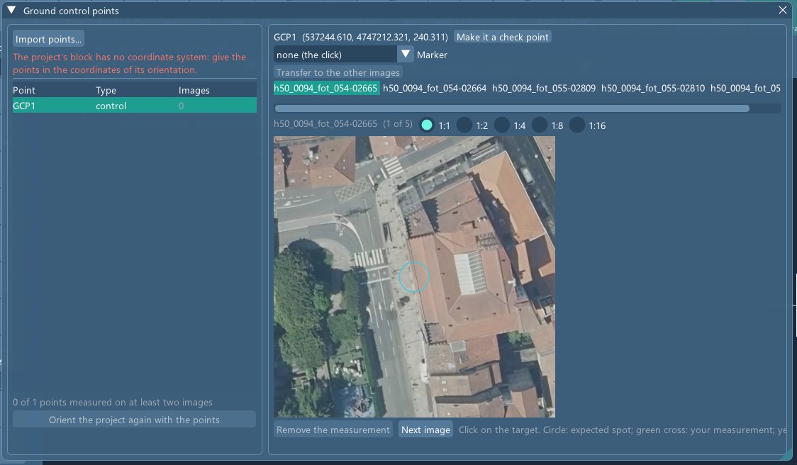
name x y h [sx sy sh] [gcp|check](or justx y h: the points number themselves) in the project's reference system (default sigmas 2 / 2 / 3 cm). Separators: space, tab or semicolon; the decimal may be a comma. If North comes before East in the file and the points fall on the images only when swapped, the columns are swapped and the window says so; it also says how many lines it did not understand. Control points enter the adjustment; check points do not, and are reported apart. - Choose a point: the images that see it are proposed, the most central first, with the predicted position. Zoom 4:1 (enlarged, to get close to the target) to 1:16 (or the wheel), click the target. Marker (circle-square or cross-checkerboard) refines the click to the centre of the target.
- The measure is transferred to the other images by correlation (yellow cross; manual measures are green). Next image or N; Remove the measurement.
- A point needs measures on at least two images. Measures that do not fall on the same target are reported.
- Checking the orientation. The list shows X, Y, Z of every point and, for points read on at least two images, the Offset: where the current orientation puts the point, minus the survey. Hovering gives dX, dY, dZ; the mean is under the list. It works on an imported orientation too, without triangulating again. Go to the point takes plan and stereo there. An offset of tens of metres in height alone means two kinds of height (ellipsoid and sea level): choose the kind when importing the orientations.
- Orient the project again with the points.
The points and measures are saved in dataset\gcp_points.txt and
gcp_measures.txt (name image x y, pixels of the original image, origin at the
top-left corner).
8.4 Systematic models
| Model | When to use it |
|---|---|
| Rolling shutter (drones) | Cameras whose sensor is read line by line: the motion during the readout is estimated per image. On a DJI block it brought the residuals from 1.7 to 0.66 px. |
| GNSS per strip: offset / offset and drift | Navigation GNSS with a bias that changes between strips. Without ground points position and rotation of the block then rest on the a-priori values: the report warns. |
| Lever arm [m] | Antenna minus projection centre in camera axes (x right, y down, z along the view: an antenna above a nadir camera has negative z); fixed, or estimate. |
| GNSS file with attitude, boresight | A GNSS file with omega phi kappa (IMU,
degrees): attitude observations, and optionally the boresight estimated. |
| Atmospheric refraction | Calibrated metric cameras at high altitude. The block declares it and the stereo applies it. |
Lever arm, boresight and strip offsets are correlated with each other without ground points or crossing strips: the report shows their sigmas.
8.5 Result, verdict and report
The running window shows the phase (reading, finding points, matching, tie points, first orientation, bundle adjustment, writing), the time left and elapsed. You can close it: the work goes on. Cancel stops at the next step; the points found are reused next time.
The result opens with a verdict:
| Verdict | Main reasons |
|---|---|
| Good | The block meets every threshold. |
| To check | Less than 98% of the images oriented; RMS of the image residuals above 1 px; sigma0 outside 0.6–1.6; more than 2% weak images (fewer than 100 observations); RTK residuals above 10 cm; control or check points above 3 GSD; ground points measured on fewer than two images. |
| Problem | Less than 80% oriented; RMS above 2 px; control or check points above 10 GSD. |
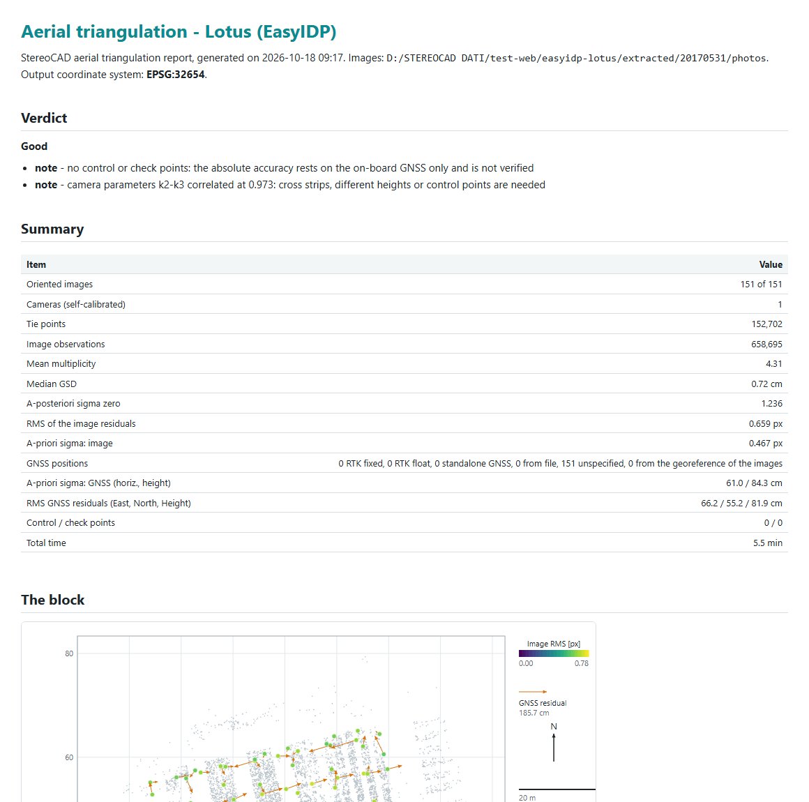
Notes accompany it: no ground points, correlated camera parameters, free datum (no GNSS and no points: arbitrary scale). Then the table (images oriented, cameras, tie points, sigma0, RMS, median GSD, reference system, time) and Open the report / Open the folder. In a project the oriented block is imported at once and becomes the active orientation; the stereo is ready.
The report () is a self-contained HTML page, with the same content in Markdown and SVG figures, in the language of the program: verdict, summary, the block (map, coverage), tie points (multiplicity, residuals), adjustment phases, systematic models, cameras (values, sigmas, correlations, residual field, distortion), control and check points, exterior orientations. shows the oriented block in 3D: images coloured by confidence, RMS, observations or GNSS residual; tie points by error or rays; ground points.
Files written in at\ of the orientation: colmap\ (the model, with
crs.txt), orientations_opk.txt (label X Y Z omega phi kappa, degrees),
calibration.txt, report.html / report.md,
summary.json, and the feature cache.
8.6 Earth curvature
The adjustment is computed in a local Cartesian frame, so the curvature is inside it. When the block is used in the projected system, StereoCAD applies the curvature (about 8 cm at 1 km from the nadir) together with the grid scale factor in the stereo, the intersections and the ground points. It is automatic. StereoCAD64 did not apply it. Blocks imported before this version gain it when imported again.
9. Dense cloud, DSM and orthophoto
From the oriented images StereoCAD generates the dense point cloud, the DSM and the true orthophoto of the active orientation, and shows them in the plan and in stereo. DSMs of other programs can be imported.
9.1 Generating
opens the panel; + New dense cloud:
| Option | Meaning (default) |
|---|---|
| Resolution | Full / Half (recommended) / Quarter (quick). Full costs about four times half. |
| Matching on | NVIDIA GPU if present, else CPU (default) or CPU only; the line below says which device is used and why. |
| Fill the flat areas from coarser levels | On: holes in texture-poor areas filled from coarser levels (water left empty), about 25% more time. |
| Kind of object | Automatic (3D when most images are oblique or terrestrial), Terrain and buildings (2.5D), 3D object. |
| Area | The whole block, or a polygon: Draw area (also ): left click adds a vertex, right click or Enter closes, Backspace removes the last vertex, Esc cancels. |
| DSM › Rebuild the roofs (DSM and cloud) | On (9.3). |
| DSM › Regularized surfaces | Automatic: on for satellites and for images of 8 cm or more. The DSM is made of smooth planes with sharp steps at the walls; the cloud lies on the surfaces, the points too far from them (the “fog”) are removed and the cells left empty get a point marked synthetic. On aerial blocks the facades stay. Always / Never to force it. |
| Orthophoto › Make it after the DSM | On: the orthophoto follows and goes into the drawing. |
| Mesh › Solid surface (mesh) | Off in 2.5D, always on in 3D. |
Generate dense cloud and DSM starts the job in the background with its phases (choosing the pairs, matching, merging and cleaning, common grid, writing, preparing the view, orthophoto), a progress bar and the elapsed time; a small window shows it when the panel is closed. Cancel stops between images; generating again with the same resolution, kind of object and area continues where it stopped, reusing the images already matched. When a project with a block but no dense cloud is opened, StereoCAD proposes to generate one, with the time each resolution would take on this computer (Not now, Never for this project).
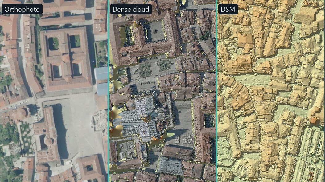
9.2 Products and files
The panel lists the products of the active orientation: each dense cloud with its DSM, orthophoto
and mesh, with Export... (DSM, orthophoto), Make / In the drawing (orthophoto) and
Delete (permanent, after confirmation). Each layer is a folder in
prodotti\ of the orientation:
| File | Content |
|---|---|
cloud.laz | The cloud: XYZ, RGB, source image, number of rays, confidence (intensity); reference system of the block. |
dsm.tif | Float32 GeoTIFF, NoData −9999, cell twice the GSD of the matching level. |
dsm_fill.tif | Mask of the cells changed by the roof rebuilding: 1 hole filled with a roof, 2 measure replaced, 3 hole interpolated. |
ortho.tif | True orthophoto, tiled JPEG GeoTIFF with overviews. |
mesh.ply | The solid surface (when made); the measured cloud is then
cloud_matched.laz. |
report.json, area.txt | Numbers of the run; the area polygon. |
A Base cloud (automatic) made from the reference surface and the tie points is available before any dense cloud.
9.3 Roof rebuilding
Roofs are recognised by geometry (raised areas with a drop at their border); their planes or curved
surfaces are estimated from the parts measured with certainty. Holes are filled with those surfaces and
uncertain measures off the surface are replaced (eaves, skylights, chimneys and trees stay as
measured). In the DSM the changed cells are in dsm_fill.tif; in the cloud the replaced
points are removed and synthetic points are added, marked class 6 (building) with the LAS
synthetic flag and confidence 0. Untick Rebuild the roofs (DSM and cloud) (or
--no-roof-fill) to keep the DSM as measured. It is always off in 3D mode.
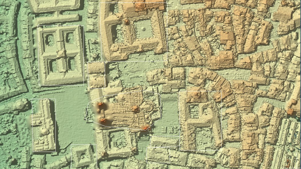
9.4 Display and use
- In stereo and In the plan; colour From the images (RGB), By height, Image (3D view), Confidence; point size; Splat (round points); Hide synthetic points; Filter by confidence; Rebuilt roofs (cyan hole filled, orange measure replaced).
- Plan layers: Orthophotos / DSM / Cloud / Drawing in the plan (Cloud menu or toolbar).
- The DSM gives the cursor its elevation when the stereo is off, feeds Drape on terrain, checks the automatic elevation and drives the navigation on the cloud (11.2).
- : right drag orbits (Ctrl rolls, Alt turns about the vertical), middle drag pans, wheel zooms.
- Block flown off east-west. The stereo keeps the flight direction horizontal on the screen (the eyes want the base there): with the plan north-up, a move to the right in the plan went across the stereo. With the stereo on, on these blocks the 3D view opens by itself looking down, turned like the stereo: right in the plan is right in the stereo, north is on the triad. Draw there as in the plan; for the north-up plan again, 3D on the toolbar.
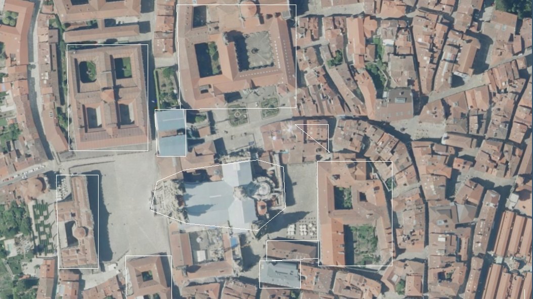
9.5 Orthophoto in the drawing
The orthophoto is made on the final DSM: each pixel from the nearest image that sees the point, seams blended and colours balanced. (or Make in the panel) makes it; it is placed in the drawing on the layer Ortofoto, under everything, and exported with the DXF / DWG (15.2).
9.6 Contour lines
draws the contour lines of the ground of the dense cloud shown. The DSM is the surface - roofs, trees, cars - so the ground is first filtered from the points of the cloud with the ground filter (SMRF, with its rules for photogrammetric clouds). Only the terrain model is made: the cloud keeps its classes. The filter runs when the window opens, with its bar and Cancel (a drone block of 230 million points: about 20 s), and is kept for that cloud while the project stays open.
- Interval and Index every: proposed from the relief of the ground (about thirty levels), then yours.
- Shortest line kept and Vertex thinning: shorter lines are noise and are dropped; the thinning never moves a line more than the slope allows, so two lines never cross.
- Write the elevation on the index contours: the index line opens a gap where its elevation is written; height and spacing of the text are proposed from the extent of the ground.
- Where the ground was extrapolated outside the survey nothing is drawn, unless asked.
- Layers CURVE_LIVELLO (ordinary), CURVE_DIRETTRICI (index) and CURVE_QUOTE (elevations), all editable.
- The area: the dense cloud area polygon when one is drawn (), else the whole cloud.
- Undo the drawing removes the lines and elevations of the last run only, to draw them again with other parameters or on another area.
The DTM out of the program. Contour lines save the terrain beside the cloud: in the dense cloud panel, on the DTM row, Export... makes a GeoTIFF copy and To CAD (DXF)... a DXF drawing of 3D faces (layer DTM_FACE) or points (layer DTM_POINT), at the grid step you choose; the window says how many entities and MB. Outside the survey area nothing is written.
9.7 Importing a DSM
In the panel, Imported: Import DSM... (a north-up GeoTIFF, copied into the project), in the block's coordinate system. Point clouds are not imported: work on clouds belongs to StereoCloud3D. A cloud imported by an earlier version stays visible.
9.8 Reference and accuracy report
measures how good a surface is. A reference (a laser survey, a ground truth, another program's DSM) is imported once, seen in the plan, and any DSM of the project is compared with it - or two DSMs made by different methods are compared with each other.
- Reference: a DSM GeoTIFF or a LAS/LAZ cloud. A cloud becomes a grid of its highest point per
cell, as a DSM sees the tops. Give its coordinate system when the file does not say it (for example
EPSG:32721) and whether its heights are ellipsoidal or above the sea: a different system
is converted, and different height datums are brought together with the EGM2008 geoid. It is copied
into the project (folder
riferimento); the original file is only read. - Comparison: Product (a DSM of the project) against a reference or another product, on all of it or only inside the drawn area. Both surfaces go on a common grid (the coarser cell; the finer surface averaged in each cell).
- Results: the spread of the errors (NMAD, without the gross ones), the systematic offset
(median), the share within 1 m of the median, RMSE, completeness and the horizontal shift that fits
best - for all of it and for flat surfaces. Open the report shows the full report: the same
figures for flat surfaces, slopes and edges, 68/90/95% of the errors, the histogram and the map of the
difference. It is written in the project's folder
accuratezza, withdifference.tifandreport.json. - In the plan: Reference and Differences on the bar Show - the difference centred on its median, blue where the product is lower, red where it is higher.
How to read it: the median is the offset of the whole surface (a height datum, a geoid, an
orientation); NMAD is the spread an operator sees; the share within 1 m of the median on flat
surfaces is the usable measure. Edges (steps over 1.5 m) depend on the plan position more than on the
height: a small shift in plan makes large differences there. From the command line:
accuracy_report --product dsm.tif --reference laser.tif --out folder.
10. The workspace
Once a project is open, StereoCAD shows the plan (the Drawing tab) in the main window, with the CAD toolbars above and to the left, the Layers and Project tabs on the right and the Overview of the block below them. The stereo model is shown on the stereo monitor (or monitors): the main window is where the mouse and the keyboard work.
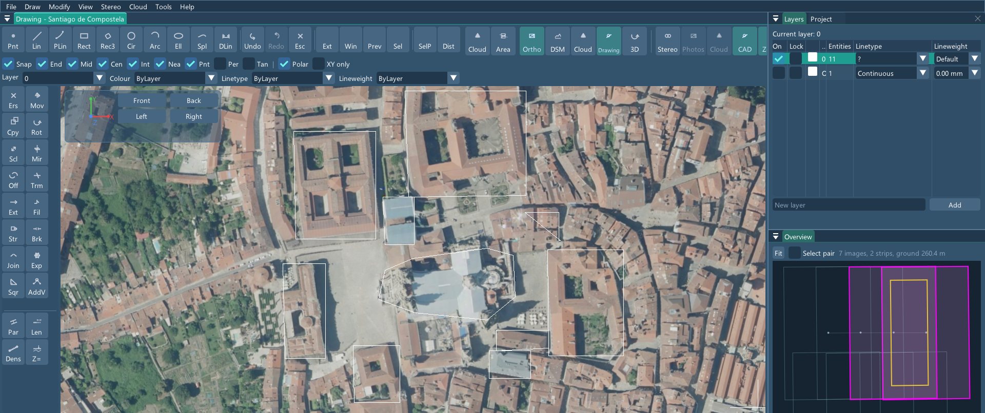
10.1 Menus
| Menu | Contents |
|---|---|
| File | New project, Open project, Image orientation, Recent projects; Import drawing (DXF, DWG, VEC, SFI), Update an existing map, Export DXF / DWG, Export to GIS (SHP / GeoPackage); Import photogrammetric dataset, Bundle view, Project tree, Ground control points, Orientation report; Save project, Close project, Exit. |
| Draw | Points, lines, polylines, rectangles, circles, arcs, ellipses, splines, dimensions (chapter 13). |
| Modify | Undo / Redo, the edit commands, polyline clean-up, elevations, selection, measure, clipboard. |
| View | Zoom extents, window, previous, selection, in, out; Regenerate. |
| Coding | Feature codes and attributes (chapter 14). |
| Stereo | Stereo on, navigation, pairs, view, automatic elevation, reference surface, mark, output and devices (chapter 11). |
| Cloud | Dense point cloud panel, dense cloud area, reference and accuracy, 3D view, plan layers, cloud colours, orthophoto into the drawing, contour lines (chapter 9). |
| Tools | Pointing devices (SpaceMouse, photogrammetric mouse), Keyboard shortcuts (chapter 12), Satellite sensor library (7.3). |
| Help | User Guide (F1), Keyboard shortcuts, Coming from StereoCAD64 and Troubleshooting (sections of this guide), Language, License status, About StereoCAD. |
While a long job runs (import, export, orientation started from a project), the whole menu bar waits: nothing may touch the project or the drawing until the job ends.
10.2 Toolbars and plan layers
The top strip holds the drawing commands, Undo / Redo / Esc, the zoom buttons, selection and measure. Buttons with variants (circle, arc, dimensions, selection, measure) list them with a right click. Then Dense and Area open the dense cloud panel and trace its area, 3D opens the rotatable 3D view. The last group drives the stereo: Stereo (on / off), Photos and Points (navigation on the images or on the dense cloud), CAD (drawing over the stereo), Scroll (free zone of the mark, beyond it the plan scrolls), Tone (brightness and contrast) and, on the cloud, Relief.
What the plan shows is chosen inside the plan, top right beside the block buttons:
Show: Orthophoto, DSM (shaded, off by default), DTM (the terrain),
Cloud and Drawing, from bottom to top; a lit button is shown. A button in amber is a
product the project could make but has not made yet: its tooltip says how, and a click opens the
window that makes it. What the block cannot make (the orthophoto of a satellite block) is not listed. A product just made or
imported (orthophoto, dense cloud, DSM, terrain, contour lines) is switched on by itself. The terrain
is the ground filter of , saved next to the DSM as
dtm.tif (and dtm_mask.tif, where each cell comes from) and read back the
next time while the cloud does not change; Filter the ground again in the same window makes it
anew.
The left column holds the edit tools and four groups of StereoCAD tools (parallel, lengthen, densify, constant Z) whose variants open with a right click.
10.3 Panels
- Layers: the layers of the drawing (13.4).
- Project / Project tree (File › Project tree): the dataset, its orientations and their products (6.5).
- Overview: the image footprints by strip, the current pair and the removed pairs (11.3).
- Command line: typed commands, prompts and messages (13.2).
- Coding: the feature code panel, a tab beside the Layers (14).
- Dense point cloud: products of the active orientation (9).
- Bundle view: the oriented block in 3D, cameras and tie points (File › Bundle view).
10.4 Status bar and language
The status bar at the bottom shows the last message, the coordinates of the cursor and, while a job runs, its phase and elapsed time. The interface language is chosen in : Auto (system), English, Italian, French, German, Spanish or Brazilian Portuguese; the choice is saved for this computer. The orientation report is written in the language of the program.
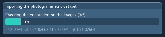
10.5 Ask Stereo AI
The green Ask Stereo AI button in the menu bar (also ) opens the assistant Stereo AI, which knows this guide and sees the state of the open project (blocks, frames, cameras, coordinate systems, orientations, products, last lines of the log). Write the question as you would to an expert colleague: what you want to get, on which block or product, what result you expect. Stereo AI answers with the steps and names menus, windows and buttons; it does not open windows or change the project: the operator opens them and starts the work. How to use it, at the top of the window, shows the explanation and a few example questions: a click puts one in the field. The questions and the project state (never photos or drawings) go to an external artificial intelligence service; the answers do not use AI credits.
The main windows have a small Ask Stereo AI button: , , the image orientation (aerial triangulation) settings, , and the ; the menu ends with . The button opens Stereo AI with a question about that window already written in the field and not sent: complete it with what you want to get (the block, the product, the result expected), change it as you like and send it with Send. Stereo AI also sees which windows are open.
The AI credits are always at the right end of the status bar: the coloured bar is what is
left of the allowance (green, amber when running low, red when used up). A click, or
, opens the balance, this month's use and the latest
movements. For now a top-up is ordered by writing to info@menci.com and paid by bank transfer;
the credits are added to the balance once the payment is recorded. Buying by card from the program will come
with an update: until it is active, Top up credits says so and gives the same address. Ask Stereo AI does not use credits; the functions that
say so use them, such as Stereo AI: what this project allows. Every paid year includes 500; topped-up
credits do not expire while the contract lasts and at renewal are added to the 500
(5.3).
11. Stereo viewing
The stereo model is built from two oriented images. The stereo monitor only displays: you move the floating mark from the main window, with the mouse on the plan, the photogrammetric mouse, the SpaceMouse or the keyboard, and you draw with the CAD commands as in mono.
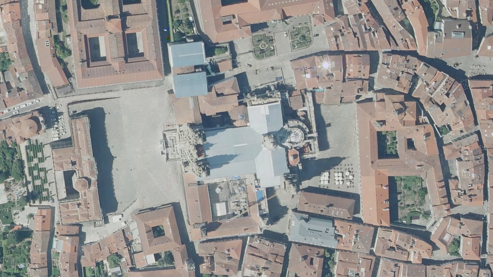
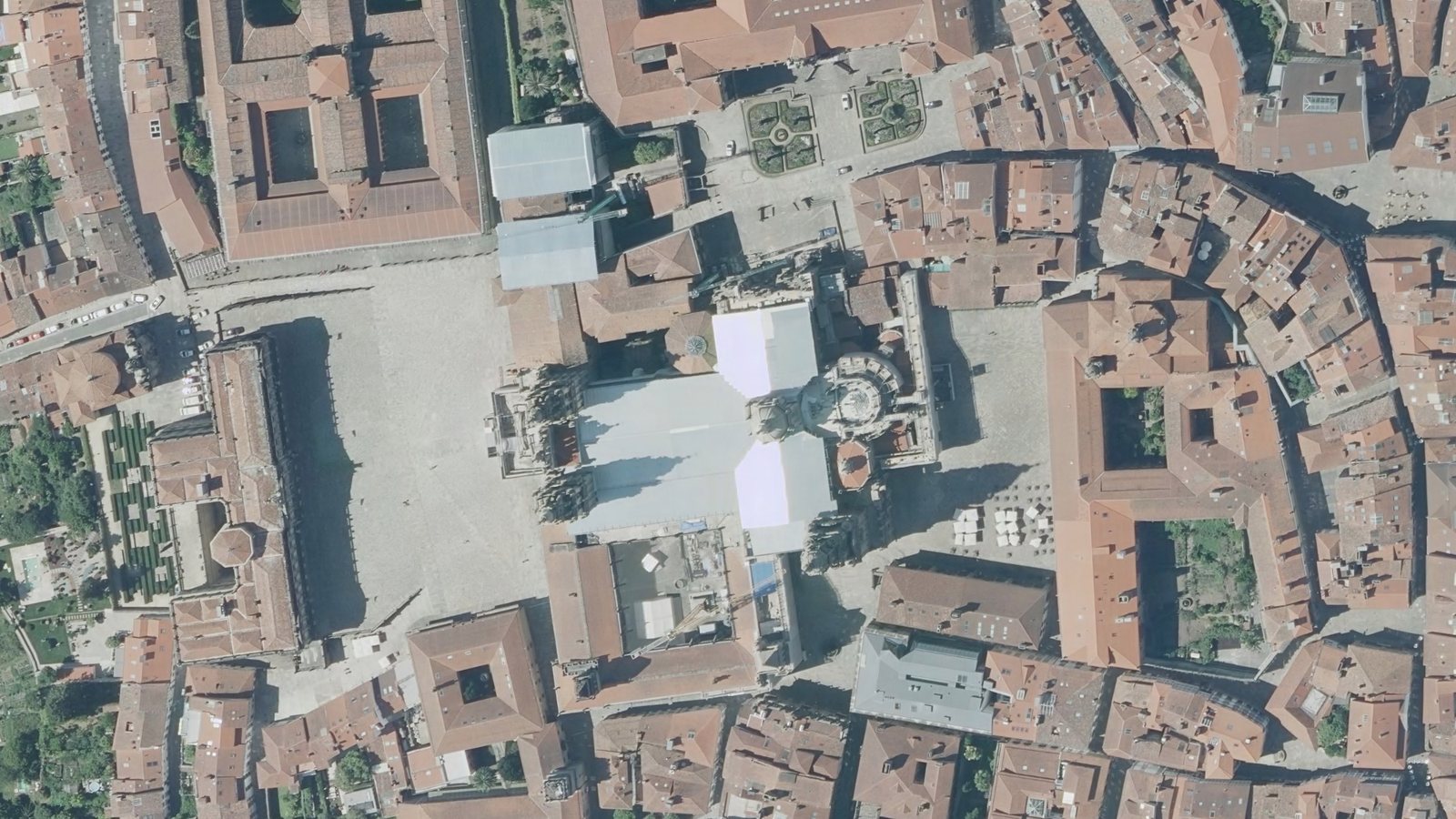
11.1 Output and devices
Choose the display layout in . All five layouts are listed; those this workstation cannot run are greyed out with the reason (for example Needs 2 extended displays (Win+P → Extend)).
| Layout | What it does |
|---|---|
| Mono | Single monitor: interface and mono view on the Windows primary display. |
| Stereo SBS (dual monitor) | Interface and mono preview on the primary display; side-by-side stereo on the secondary one. |
| Stereo Top-Bottom (dual monitor) | Top-bottom stereo on the secondary monitor, left eye in the upper half: for passive 3D panels set to Top-Bottom input. |
| Beam-splitter mirror (triple monitor) | Interface on one display, the left and right eyes on the other two, which face each other across a semi-transparent mirror: each eye sees one monitor through polarising glasses (passive polarisation). |
| Active shutter (IR emitter) | Frame-sequential: a 120 Hz panel alternates the two images and the active shutter glasses darken the other eye in sync, driven by an infrared emitter on USB. |
- Beam-splitter mirror options: beam-splitter mirror on two monitors (cloned outputs), quad-buffer passive, mirrored reflected eye, the monitor of each eye, the side of the interface, and Auto-assign eye monitors from desk layout.
- Active shutter options: who produces the two eyes (automatic, the graphics driver with quad-buffer, or StereoCAD with page flip and USB emitter) and the shutter delay (default 5385 µs). Choosing active shutter starts a 15-second trial: confirm it in the Stereo output safety check window, or it rolls back by itself. An unconfirmed trial leaves the stereo output off at the next start, with Re-enable stereo output.
- Adjustments: Swap left / right and Stereo calibration, a test pattern (red to the left eye, blue to the right, a white cross in both).
Then (or the Stereo button) shows the current pair; it centres the plan on the mark and gives the stereo the scale of the plan. It needs an open project with a photogrammetric block.
11.2 Navigation: on the images or on the dense cloud
- Navigate on the image pairs (F6 in the StereoCAD key set): the photographs are resampled on the navigation plane, the horizontal plane at the elevation of the mark. The pair changes by roaming with no jump of scale, rotation or position. Moving the mark keeps the elevation; a jump longer than half the view at zoom 1:1 (a far click on the plan) lands on the reference surface's elevation instead.
- Navigate on the dense cloud (same key): the stereo shows only the dense cloud (or the
shaded DSM), the drawing and the mark, seen by a virtual stereo camera that follows the mark: one
continuous space, no pairs. Cloud relief (×0.25 to ×4) sets the depth: 1 is the
B/H of the block's photographs. With a dense cloud or DSM (chapter 9) it shows
them; without, it shows shaded the reference surface the program measures by itself at the opening
(a 5-20 m grid: enough to navigate in depth). A project without a dense cloud then gets a light one,
made by itself in the background: the navigation cloud (
densa_navigazione), at the level that keeps it under 20 million points (from seconds to a few minutes; the window at the bottom right shows its bar and Cancel). Stopped, it does not start again by itself in that project. The automatic elevation rests in this mode, because it measures on the images. - CAD drawing on the stereo (Shift+F6): the drawing over the stereo, on the photographs and on the cloud alike. On by default.
The navigation mode, the relief, the overlay, the tones and the removed pairs are saved in the project: a project closed in cloud navigation reopens in it.
The stereo's start. The stereo starts at the ground elevation measured on the images, never at a guessed one. The first time a block opens the program measures the reference surface (some tens of seconds; the status bar shows Stereo: the reference surface is being measured with the percentage) and the stereo starts when it is ready; from the next openings it is read from the project and the stereo starts at once. When the ground cannot be measured on the images, the status bar says so and the surface is measured from the stereo's elevation.
11.2.1 Moving around the model
The stereo follows the mark, and the mark is driven from three places. Stereo > How to move around opens this reminder at any time; it appears by itself the first time the stereo is switched on.
- The mouse on the plan. The mark goes where the mouse is. It stops at the plan's edge: hold the mouse still on the edge and the plan rolls on.
- Continuous roaming (F10, Stereo > Continuous roaming). The mouse has no edges, as in StereoCAD64: it stays hidden on the plan and the mark follows it at the stereo's scale, endlessly. It is the way for who wants to look only into the stereo. Back to the menus: Esc or F10 again. If the pointer reaches the stereo monitor, where it would be invisible and nothing would answer, it comes back to the plan by itself and continuous roaming starts.
- The Overview. A click takes the plan and the stereo there, with the stereo off too (then the plan moves and the stereo will start there). With the left button held down and dragged, plan and stereo follow the mouse. With the mouse stopped on the map, after a moment, the mark follows it without pressing anything. Back on the plan, the mark stays where it was taken: it does not jump to the mouse. Under the image footprints you see the photographs; ground control points are green triangles, check points blue.
Who looks only into the stereo finds the useful messages inside it: the mouse off the plan or on its edge, the stereo held, the pair locked, the point reached. Stereo > Messages in the stereo switches them off.
11.2.2 Visit point
Stereo > Visit point (Ctrl+G, also from the right-button menu on the plan and on the Overview) takes the plan and the stereo to a point. Type X and Y and, if needed, Z; without Z the mark lands on the navigation surface. The three coordinates can be pasted together into the first field, with a comma or a dot as decimal mark. With Scale 1:1 one image pixel is one screen pixel on the plan and in the stereo. The plan shows a ring on the point reached.
With the stereo off the plan moves, and the stereo will start from that point. If no pair sees the point the window says so: the plan goes there, the stereo stays where it was. On the plan, at 1:1, the background photographs are the navigation surface's light mosaic and look blurred; the sharp view is in the stereo, or on the plan with an orthophoto.
The same window lists the project's ground control and check points: a click on a row goes to the point, at its surveyed height; Previous and Next walk through them. Go to the point in the Ground points window does the same.
11.3 Pairs
StereoCAD chooses the pair as StereoCAD64 did: among the near-nadir images that see the point, the one with the nearest projection centre and a partner on the same strip along the flight line. The pair is kept while the point stays inside both footprints with a 5% margin; near the border a new pair takes over only if it is clearly more central. Nearby images are loaded in advance in eight directions.
On satellite blocks each scene is paired with the partner that gives a B/H close to 0.6, among those with a B/H of at least 0.15: two views of the same pass, with almost no base, do not make stereo.
| Stereo › Pair | What it does |
|---|---|
| Roaming (automatic pair) | When the mark leaves the central area of the pair (yellow on the plan), the best pair for that point takes over: same point, same place, same zoom. On by default. |
| Lock pair | Keeps the current pair: no roaming. |
| Change pair | The next pair that sees the mark point; repeated, it cycles through them. |
| Remove pair | The current pair is never chosen again in this project (saved). Restore removed pairs brings them back. |
| Pairs across strips | Pairs made of two adjacent strips flown in opposite directions. |
| Stereo turned like the plan | On (default): the left image is chosen so that east is to the right, as in the plan, and the mouse moves the images the same way in both windows. Off: the images as they were taken, as in StereoCAD64. The depth is right either way. |
| Pair › img - img | A fixed pair from the list (each image with its nearest neighbour). |
In the Overview, Select pair builds a pair by hand: click the first image, then the second (orange = a stereo model, red = not; Shift on the second click locks it). A double click visits a point; the right-click menu has Stereo here, Lock pair, Change pair, Remove pair; the wheel zooms, the middle button pans.
11.4 View, zoom and tone
- Plan and stereo in step (default on): one ground scale for plan and stereo. From near, the real photograph lies under the plan, as sharp as the stereo, on the navigation surface (layer Orthophoto); from afar the light mosaic stays. It helps one find the way and is not an orthophoto; a project orthophoto is drawn over it. With the Orthophoto layer off it comes too when the cloud's points stand apart: from near the points give way to the photograph. The wheel on the plan zooms both; Ctrl+wheel and Stereo zoom in / out zoom too. Off: the stereo has its own zoom (Ctrl+wheel). The keypad's + and - zoom in and out by two at a time, also when looking only into the stereo. The stereo does not go further out than the common area of the two images filling its screen, even with the plan on the whole block: from there the first notch in enlarges at once. Stereo 1:1 shows one image pixel per screen pixel; Fit shows the whole overlap.
- Fixed mark (default on): the mark stays at the centre of the stereo window and the model moves under it, as on analytical plotters. Off: the mark is where the mouse is on the image.
- Free zone of the mark (off by default: switch it on here or with Scroll): the mouse moves the mark freely in the central part of the plan (the rectangle); beyond it the plan (and the stereo) scroll towards the mouse, faster the further out. Looking only at the stereo, you roam without stopping. If it gets in the way, switch it off here or with the Scroll button.
- Free zone size: how much of the plan stays free, 30% to 90% of its width and height (50% at the start). Larger: the plan scrolls only near its edges. Saved in the project.
- Pair footprints on the plan: the footprints of the two images, their central area (yellow) and the ground seen by the stereo window.
- Centre the plan on the stereo.
- Brightness and contrast (also the Tone button): for all images and for the left and right image on their own; display only, saved in the project.
- Image view (monoscopic): the left image of the model in a tab of the main window, where the mouse moves the 3D cursor as in StereoCAD64's mono mode.
11.5 The floating mark and its elevation
With the stereo running, the mouse on the plan gives the mark its X and Y at the mark's elevation. On the photographs the elevation stays constant while the mark moves (the images are rectified on the plane of that elevation); you change it with:
| Input | Effect |
|---|---|
| Shift+wheel | Mark up / down: one notch = one screen pixel of parallax at any zoom. |
| Ctrl+Shift+wheel | Fine: one tenth of that. |
| SpaceMouse twist | Clockwise = up (12.1). |
| Photogrammetric mouse wheel or trackball | Forward = up (12.2). |
| Mark up / down one step | Commands without a default key: assign them in Tools › Keyboard shortcuts. |
| Z, F7, Ctrl+Shift+Z | Automatic elevation (11.7). |
In cloud navigation the mark follows the dense DSM under the mouse (Stereo › Reference surface › The cursor follows the DSM (cloud)); an elevation set by hand or measured is kept until the mark moves two grid steps away.
sets its shape (point, point and cross, point and X, cross, X), ring instead of disc, colour, size and thickness, and Coordinates in the stereo (X Y Z), a coordinate block in each eye.
11.6 Fine pointing
(F8, on by default): during a drawing command the mouse on the plan moves the mark and the model slides under it: there is no edge to stop or wait at. The CAD crosshair follows the mark, the plan keeps the mark in its central part, and the click takes the mark's exact 3D point. It works with plan and stereo in step (the default) and when the stereo is more zoomed in than the plan; then the mark moves at the stereo's resolution. When the command ends the mouse is free again; to reach the toolbars during a command, F8 switches it off.
The same in the 3D view: during a drawing command the mouse moves the stereo mark on the ground, the view follows it and the click takes its point; the right button still turns the view, the middle one moves it and the wheel zooms, while the mark waits.
sets how far the mark moves for each pixel of the mouse: x1 a stereo pixel, x0.5 half of one (slower, for collimating), up to x2.
Holding the stereo. The stereo follows the mouse while the mouse is over the plan. To reach the menus and the toolbars without moving it: Esc (with no command running and nothing selected) or . The plan and the status bar say Stereo held and the mark turns grey. Esc again: the pointer goes back onto the mark and the mouse drives the stereo again. While a command runs, Esc ends the command first, as always.
Without Esc too: when the mouse crosses the plan (or the 3D view) quickly and leaves it for a menu or a toolbar, the mark goes back to where the hand was still a moment before, and the status bar says so. The stereo is not left where the mouse went out.
11.7 Automatic elevation
The automatic elevation measures the ground at the mark by correlating the two images along the epipolar line (normalised cross-correlation, coarse to fine, sub-pixel, least-squares refinement). A measure counts only when it passes the reliability tests (correlation, uniqueness of the peak, texture, left-right check); otherwise the elevation does not change and the mark says why.
| Stereo › Automatic elevation | What it does |
|---|---|
| Off | The elevation changes only by hand. |
| On request | Default. Z (or F7; the menu shows the keys in force) measures at the mark and puts the mark on the ground found. |
| Continuous | Measured whenever the mark stops (and a few times a second while it moves). Shift+wheel pauses it until the mark moves again. Ctrl+Shift+Z switches between Continuous and On request. |
| Measure at click | Before each digitized vertex the elevation is measured again at the mark. |
| Other images where the pair fails (aerial) | Up to five more images, at least three must agree. Default on. |
| Least-squares rescue of uncertain elevations | Off by default. |
| Measure elevation now | A single measure. |
A ring around the mark tells the result for a moment: green reliable, yellow thin margin or disagreement with the dense cloud, red failed, cyan elevation taken from the cloud. When a dense cloud exists it narrows the search and checks the measure; the status bar shows both values when they disagree.
11.8 Reference surface
is a coarse grid (5–10 m) measured on the stereo images in the background when a block is opened. It gives the automatic elevation and the dense cloud their search range. The menu shows its state (step, measured and filled percentage) and Recompute.
12. Pointing devices and keys
StereoCAD reads the SpaceMouse, the Stealth V / Stealth Z photogrammetric mice and a trackball for the elevation directly through Windows: no Menci driver is needed. Every command can be put on any key, starting from the keys of StereoCAD or from those of StereoCAD64.
12.1 SpaceMouse
. The SpaceMouse moves the view you are using: the 3D view when it is open, otherwise the stereo model (the plan follows it), otherwise the plan. The twist changes the elevation of the mark in every view.
Without the 3Dconnexion driver the SpaceMouse is read directly and the window sets it:
| Cap movement | Default function |
|---|---|
| Push left / right | Pan sideways |
| Push forward / back | Pan up / down |
| Pull up / press down | Zoom |
| Tilt forward / back | Tilt the view |
| Tilt left / right | Rotate (heading) |
| Twist | Mark elevation (clockwise = up) |
Each axis can be inverted and has a speed (0.1–10); Dead zone (default 0.06), Response (default 2) and Only the strongest movement apply to all. At speed 1 a full deflection gives 20 pixels of parallax per second in elevation, whatever the frame rate. The keys of the SpaceMouse run commands: by default Menu = this window, Fit = reset the stereo view, T = plan view, 1 = automatic elevation now, 2 = change pair, Esc = end the CAD command. Restore defaults brings them back.
With the 3Dconnexion driver (3DxWare 10.8.12 or newer, in builds with the driver interface) speeds, axes and buttons are set in 3Dconnexion Settings, the same for every program.
12.2 Photogrammetric mouse: Stealth V, Stealth Z
,
or the same item in the Stereo menu.
Tick Use the photogrammetric mouse, then choose the device from the list (* marks
the one just moved) or press Press a button on it... and press its right, middle or side
button. The device is remembered; moved to another USB port it is found again by its vendor and
product id.
| Model | Elevation from | Default buttons |
|---|---|---|
| Mouse with extra buttons | wheel | X1 = automatic elevation, X2 = change pair |
| Stealth V | wheel | StereoCAD64's table: 1 zoom in, 2 Enter, 3 point, 4 zoom out; N S W E carry commands in four layers (alone, +SL, +SR, +SL+SR) |
| Stealth Z-Mouse | wheel | 1–5: zoom in, Enter, point, zoom out, change pair |
| Trackball for the elevation | ball | right = automatic elevation, middle = change pair |
- The left button is always the point. Two buttons can be SL and SR, held like Shift: every other button then has four commands, as in StereoCAD64.
- Elevation from: the wheel, the side wheel, the ball (forward = up) or nowhere. Wheel forward = mark up, as Shift+wheel. Elevation speed is in pixels of parallax per notch (or per 8 ball counts); Ctrl = fine; Invert.
- XY speed (0.1–5): the pointer follows the photogrammetric mouse slower or faster, without Windows' acceleration; the normal mouse is not affected.
- The elevation works only with a stereo model open; otherwise the wheel zooms as usual. A button with a command does not also make its normal click.
- While the window is open a button only lights up its row: use it to check the mapping.
- Model defaults restores the buttons, elevation and speeds of the model.
12.3 Trackball for the elevation
Choose the model Trackball for the elevation for a Kensington Expert Mouse or similar beside the normal mouse: rolling the ball forward raises the mark, the pointer stays still while it rolls (the normal mouse still moves it), and it is free again shortly after the ball stops. A Kensington or another trackball chosen as the device takes this model by itself. With the stereo off there is no mark: the ball raises and lowers the elevation of the plan cursor, 0.1 m a notch times the Z speed (Ctrl: 0.01 m), starting from the elevation shown there; the coordinates and the digitized points take it until the stereo mark moves again or the project is closed.
12.4 Keyboard shortcuts
puts any command on any key with Ctrl / Shift / Alt:
- Start from: StereoCAD keys or StereoCAD64 keys (chapter 16 lists both).
- Change, then press the new key (Esc cancels). A key does one command: given to another, it leaves the first, and the window says so. No key and Default per row; Undo my changes for all.
- The keys the CAD reads as keys cannot be assigned: Enter, Esc, Backspace, Del, Ins, Tab, Space, arrows, PgUp / PgDn.
- The menus show the key in force. The changes are saved for this computer
(
keyPresetandkeyBindingsinsettings.json).
13. CAD drawing
StereoCAD draws with the native CAD engine it shares with StereoCloud3D. The drawing is in world coordinates of the project's reference system, with real Z: every vertex digitized in stereo takes the 3D point of the mark.
13.1 Drawing and editing
| Menu | Commands |
|---|---|
| Draw | Point; Line; Polyline; Rectangle (2 corners); Rectangle (3-point, rotated); Circle (Center-Radius, Center-Diameter, 2 Points, 3 Points); Arc (3 Points and the start/center/end variants, Continue); Ellipse; Spline; Dimensions (Linear, Aligned, Radius, Diameter, Angular, Ordinate). |
| Modify | Undo, Redo; Erase, Move, Copy, Rotate, Scale, Mirror, Offset, Trim, Extend, Fillet, Stretch, Break, Join, Explode, Square; Add vertices, Reverse direction, Close polylines, Divide into parts, Offset 3D, Match properties; Parallel..., Stereo parallel...; Lengthen, split, clip (Lengthen / shorten, Break at intersections, Clip with fence, Reshape); Polyline cleanup (Densify, Smooth line, Simplify, Remove duplicate vertices); Elevations (Constant height, Interpolate Z between ends, Level to contour interval, Drape on terrain); Selection; Measure (Distance, Area); Cut, Copy to clipboard, Paste. |
| View | Zoom Extents, Window, Previous, Selection, In, Out; Regenerate. |
Drape on terrain needs a DSM or a photogrammetric cloud in the project. The options of the StereoCAD tools (parallel, lengthen, densify, elevations) are remembered.
Mouse on the plan: left click = point (at the mark's elevation with the stereo running), right click = Enter when a command waits for it, middle drag = pan, wheel = zoom. Without the stereo the elevation comes from the DSM when the project has one (chapter 9).
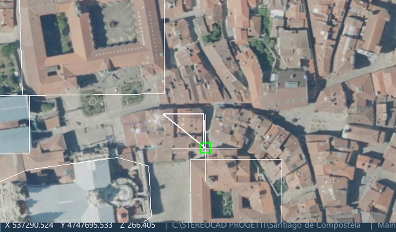
13.2 The command line
Type a command and Enter: an alias (L, PL, C,
OFF...), its full name (LINE, PLINE) or its Italian name
(LINEA, POLILINEA). While a command runs, what you type is its value
(a point as x,y or @dx,dy, a distance, an option); an empty
Enter takes the default. An empty Enter with no command repeats the last one.
A word is looked up among the StereoCAD tools first, then the CAD commands, then the feature codes
(14.2), so L stays LINE.
| Group | Aliases |
|---|---|
| View | ZE, ZI, ZO, ZP, ZW, ZS, P (pan) |
| Draw | PO point, L line, ML multiline, PL polyline, PLC closed polyline, POL polygon, EL ellipse, R2 / R3 rectangles, C circle (CR, CD, C2, C3), A arc (A3, ASCE, ASCA, ASCL, ASEA, ASED, ASER, ACSE, ACSA, ACSL, ARCC), SPL spline, I insert, B block |
| Dimensions | DL, DAL, DO, DR, DD, DA |
| Edit | U undo, RD redo, E erase, CO copy, M move, RO rotate, SC scale, MI mirror, X explode, J join, TR trim, XT extend, OFF offset, OFF3 offset 3D, BR break, FI fillet, S stretch, MP match properties, DIV divide, AV add vertices, CPL close polylines, IW reverse, AL align, SQ square |
| StereoCAD tools | PAR parallel, PARS stereo parallel, LEN lengthen, SPX break at intersections, CLIP, RSH reshape, DENS densify, SMOOTH, SIMP simplify, DUPV duplicate vertices, QZ constant Z, IZ interpolate Z, LZ contour level, DRP drape |
| Snaps | SNEP, SNMP, SNC, SNN, SNI, SNP, SNT, SNNN (none), OSON, PON |
| Selection | SLP point, SLR window, SLPG polygon, SLPL fence, SLL current layer, SLT text |
| Other | RST reset, RE regenerate, DI distance, AA area; LA points to the
Layers panel |
13.3 Object snap
The snap bar: Snap (on / off) and the modes End, Mid, Cen, Int, Nea, Pnt, Per, Tan; Polar (guides along the main angles from the last point) and XY only: the snap gives only X and Y and the elevation stays the digitizing one, the stereo mark's. The choices are saved. In the StereoCAD64 key set the F-keys switch the snaps as in StereoCAD64 (chapter 20). A feature code can force its own snaps while it is active (chapter 14).
13.4 Layers and properties
The Layers panel lists the layers with On, Lock, colour, name, number of entities, linetype and lineweight; click a name to make it current; New layer + Add creates one. The 24 classic linetypes load the first time the linetype list is opened. The properties bar above the plan (Layer, Colour, Linetype, Lineweight) sets the properties of new entities and, with something selected, of the selection.
13.5 Saving
The drawing is saved with the project (, Ctrl+S). There is no automatic save: closing a project or the program with unsaved changes asks Save the project before closing it?
14. Feature coding and attributes
In cartographic restitution every element has a code (EDIFC, EL_STR...) and attributes (use, state, name...). The code decides layer, symbology, allowed geometry and attributes. StereoCAD keeps code and attributes per entity, saves them with the drawing and writes them into the DXF.
14.1 The code library
A library is a JSON code pack in the StereoCloud3D format: each code has its names, layer and
class, and StereoCAD adds geometry (point, line, area), style (colour, linetype, lineweight, point
style, layer colour), attributes (text, integer, real, boolean, date, list of values; default,
required, width, precision, limits), rules (closed, constant Z within a tolerance, minimum vertices,
forced snaps, the command to start) and an optional key and typed alias. A library can extend a
national catalogue with "basePack": the Italian DBGT catalogue (DM 10 Nov 2011, 112
classes) is installed in codes\IT\dbgt_2011.json.
The example library codes\stereocad_dbgt_esempio.json (16 DBGT classes with
geometry, symbology, attributes, rules and keys Ctrl+1…Ctrl+9,
plus 3 studio codes) is loaded by default.
opens a .json library or a
StereoCAD64 shortcut file .shc (14.5); Save as JSON... in
the panel writes the library as JSON. Libraries and their basePack are searched in the
library's folder, then in %APPDATA%\StereoCAD\codes, then in codes\ next to
the program.
14.2 Choosing the code
- F2 (): incremental search on code, name (in the interface language and in Italian), layer and class code, accents ignored; the recently used ones first; arrows, PgUp/PgDn, Enter. Right click on a code assigns or removes its key (F1–F12, or a letter or digit with Ctrl or Alt; keys of the program are refused).
- Type the code or its alias on the command line, as with StereoCAD64's shortcuts.
CODE/CODICEopens the picker,ATTR/ATTRIBUTIedits the selection. - The code's own key, if the library gives one.
The active code makes its layer current (creating it with its colour if missing), sets colour, linetype, lineweight and point style of new entities, forces its snaps (yours come back when the code is deactivated) and starts the command of its geometry.
CODE on the command
line, or give it a key in Tools › Keyboard shortcuts.14.3 Attributes
Every entity drawn on the layer of the active code takes the code and its default values; the rules are checked (geometry, closed, constant Z, vertices) and reported on the command line and in the panel; then the attribute window opens (Enter confirms, Esc skips and keeps the defaults). Untick Ask the attributes after drawing to skip the window.
For existing entities, Shift+F2 () edits code and attributes of the selection; with several entities only the fields you change are written to all. The Coding panel (a tab beside the Layers) shows the library, the active code, the recent codes and the attributes of the selection, and assigns or removes the active code on the selection. An entity on a code's layer without its own record is "coded by its layer": it has the code but no values.
14.4 Where codes and attributes are kept
The records are saved with the drawing, beside it, in <drawing>.vec.features.json
(the CAD engine has no per-entity extended data). They follow the drawing when it is saved, copied or
moved; records of deleted entities are dropped. An unreadable file is reported and never overwritten.
A copied entity gets a new identity: it takes the code from its layer, not the values.
Your library choice, recent codes, assigned keys and the ask the attributes option are in
%APPDATA%\StereoCAD\feature_coding.json.
14.5 StereoCAD64 shortcuts (.shc) and StereoCloud3D macros
A StereoCAD64 <project>.shc (also the templates in
%ProgramData%\StereoCAD\Template) loads as a library: each category becomes a group, each
shortcut a code; the command gives the geometry (a closed outline is an area), the description the
name, the keyboard alias the typed alias. StereoCAD64 had no attributes, so the imported codes have
none: add them to the JSON. Code packs and rapid-coding macros of StereoCloud3D load as they are.
A code table in text form loads as a library too, whatever its extension: one code a line,
A50100=C:1,L,AUTOSTRADA IN COSTRUZIONE;Z:1;G:;A:A50100;L:L13,1.00;. The code is the key;
C: gives colour, geometry (P point, L line, A area)
and description; G: the group; A: the layer; L: the linetype,
kept under its name (the drawing must define it). The Z: field is not used. A
line that is not a code stops the reading and gives its number. Save as JSON... turns it into a
StereoCAD library to which attributes and rules can be added.
15. Importing and exporting drawings
15.1 Importing a drawing
merges a drawing into the project's
drawing. It accepts DXF, DWG (AutoCAD 2004–2018, converted to DXF on the way), VEC and
StereoCAD64 .sfi (a VEC under another extension). Images placed in the drawing come back
as orthophotos in the plan. A .sfi image with a path relative to the .sfi
folder is not found: only absolute paths work.
15.2 Exporting DXF and DWG
writes the drawing in world coordinates:
- DXF: R12 by default; DXF 2000 when orthophotos are in the drawing (R12 has no images).
- DWG: AutoCAD 2004 format.
- Orthophotos placed in the drawing go out with it: each image is copied into the folder
<name>_ortofotobeside the file and referenced as an IMAGE on the layer Ortofoto. A missing or rotated image, or too little disk space, stops the export. - Codes and attributes: each coded entity carries extended data of the application
STEREOCAD:FEATURE_CODE=<code>then oneNAME=valueper attribute (in DWG through the DXF 2000 it is made from).
15.3 Exporting for GIS: Shapefile and GeoPackage
:
- Shapefile: a folder
<name>\with<name>_points,_linesand_polygons(.shp .shx .dbf .prj .cpg, UTF-8). Only those files are replaced in the folder. - GeoPackage: one
.gpkgwith the layerspoints,lines,polygons. - 3D geometries (Point Z, LineString Z, Polygon Z); arcs and circles segmented every 5°.
- Fields:
layer,color,entity,id,z; points alsotext,text_h,angle,block; lines and polygonsz_min,z_max,length; polygonsarea. - The reference system is the project's (EPSG or WKT), otherwise the photogrammetric block's; it is
not asked. Without one the files have no
.prjand the log says so. - Orthophotos are not exported to GIS.
Codes and attributes (chapter 14): each file also carries the field
FEATURE_CODE (FEAT_CODE in the Shapefile, whose field names have at most 10
characters) and the attribute fields of all the codes of the drawing's layers, joined by name, with
their types (text, integer, real, boolean, date). An entity without a code has them empty (NULL), as
does an attribute without a value. A name used with two different types becomes text; a name equal to
one of the fields above gets _A; in the Shapefile longer names are cut to 10 characters
(8 + _2, _3... when two collide). Every renamed field is written in the log:
keep the attribute names short in the libraries meant for Shapefile.
15.4 Updating an existing map
compares an old 3D map (DWG or DXF) with the new survey of the project (the DSM of a dense cloud, chapter 9), finds out why they differ, writes a report for the client and corrects the map, or brings a new drawing into the map's system. Only coordinates change: images, orientations and the stereo are untouched.
- Existing map: contour lines, spot heights and 3D lines (road axes, ditches) with their heights. Layers, contour interval, scale and whether the levels are round are recognised from the file itself; buildings are left out (eaves or foot unknown, perhaps rebuilt). The map must be in the project's coordinate system, heights above the sea.
- New survey: a dense cloud of the project with its DSM. When the project has none, Analyse makes it first, at a level suited to the map's scale and to the images (about a minute on a block of twenty images), and keeps it in the project as a layer.
- From the project: the coordinate system, the height of the projection centres and the focal length (in pixels when the block has no pixel size); the last two let the report tell a wrong focal length from a map drawn from a block whose projection centres were on the ellipsoid.
- Analyse: every map line is measured on the survey (woods, crops and changed ground left out), the possible causes are tried (geoid, constant, tilt, height scale, dome, local deformation, generalisation of the contours, plan shift) and the simplest explanation that accounts for the differences is chosen. The window says the typical difference today and after the correction, the precision of the map itself, and whether the plan is shifted.
- The report (
report.html, in the language of the program: English, Italian, French, German, Spanish or Portuguese) has three parts: study of the map with its plates, diagnosis, solution with the predicted result for each cause, the stereo parallax, and what would prove the prediction wrong; it ends with why the differences do not go to zero, written for the client. - Correct the map: the old map is written corrected (heights without the systematic errors), measured again and diagnosed: the window says whether the prediction is confirmed.
- Bring a drawing into the map's system: a new drawing exported from the project gets the map's errors back, so the update joins the old map without jumps.
- Points for the plan (optional): the plan is corrected only from collimated or surveyed
points, a text file with one row per point:
name xMap yMap xTrue yTrue [check]; at least 6 points on stable features (crossroads, bridges, ditches), never buildings. A point that the others contradict is set aside and reported. - Import into the drawing adds the corrected file to the drawing, on its own layers.
- Everything is written in
<project>\aggiornamento_cartografia\<map name>\: the report,correction.json(the correction, reversible), the corrected DXF andapply_report.md. The generalisation of the contours is reported, never corrected: it is how the map was drawn.
15.4.1 Working in stereo in the map's system
Without a correction the stereo shows the true ground (the new survey) and the cursor measures true heights: the old map in the drawing stays off the ground by what the diagnosis found. To update the old map consistently with it, in the window, under Work in stereo in the map's system, press Work in the map's system:
- the old map, as it is in the drawing (the original map, not the corrected one), is shown on the ground in stereo: each of its vertices goes through the correction before it is projected into the two images;
- the cursor gives the CAD, the status bar and the stereo the coordinates in the map's system: new points join the old map without steps;
- images, orientations, the automatic elevation and the dense products stay true: the parallax does not change;
- in the status bar, beside the coordinates, MAP'S SYSTEM says it is on (a click opens the window); it stays on for the project, also when it is opened again, until Back to the true system.
What to expect: the old map meets the ground within its own precision (the report's residual, for
example 1.5 m for a 1:5000 map), not to zero; on ridges and narrow valley floors the generalisation of
the contours remains. The correction used is the chosen map's (correction.json, or
correction_applied.json when Correct used points for the plan). The 3D view and the
plan show the drawing as it is, in the map's system.
16. Keyboard shortcuts
Two key sets: StereoCAD (the default) and StereoCAD64 (the keys of the StereoCAD you come from). Choose one in and change any key there (12.4); the table lists the commands that can take a key and their default keys. Plan or stereo view: the key works with the plan or the stereo focused, and a key without Ctrl / Alt only while the command line is empty.
Generated from src/app/AppShortcuts.cpp by deploy/gen-manual-shortcuts.py. “—” = no key in that set: assign one in Tools › Keyboard shortcuts.
| Command | StereoCAD keys | StereoCAD64 keys | Where |
|---|---|---|---|
| Project | |||
New project app.new | Ctrl+N | Ctrl+N | anywhere |
Open project app.open | Ctrl+O | Ctrl+O | anywhere |
Save project app.save | Ctrl+S | Ctrl+S | anywhere |
| Drawing | |||
Undo cad.undo | Ctrl+Z | Ctrl+Z | anywhere |
Redo cad.redo | Ctrl+Y | Ctrl+Y | anywhere |
Cut cad.cut | Ctrl+X | Ctrl+X | anywhere |
Copy cad.copy | Ctrl+C | Ctrl+C | anywhere |
Paste cad.paste | Ctrl+V | Ctrl+V | anywhere |
Point at the mark (left click) cad.pick | — | — | plan or stereo view |
End input (Enter / right click) cad.enter | — | — | plan or stereo view |
Remove the last vertex cad.removeLastVertex | — | — | plan or stereo view |
Cancel the command (Reset) cad.escape | — | — | anywhere |
Repeat the last command cad.repeatLast | — | — | anywhere |
Break the line (pen up) cad.break | — | — | anywhere |
Draw point cad.drawPoint | — | — | anywhere |
Draw line cad.drawLine | — | — | anywhere |
Draw polyline cad.drawPolyline | — | — | anywhere |
Draw multiline cad.drawMline | — | — | anywhere |
| Object snap | |||
Object snap on / off snap.toggle | — | F3 | anywhere |
Snap: intersection snap.intersection | — | F2 | anywhere |
Snap: perpendicular snap.perpendicular | — | F4 | anywhere |
Snap: endpoint snap.endpoint | — | F5 | anywhere |
Snap: node (point) snap.point | — | F6 | anywhere |
Snap: nearest snap.nearest | — | F7 | anywhere |
Polar tracking on / off snap.polar | — | F8 | anywhere |
Snap only X Y (2D / 3D) snap.onlyXY | — | F9 | anywhere |
Snap: centre snap.center | — | F12 | anywhere |
Snap: midpoint snap.midpoint | — | — | anywhere |
Snap: tangent snap.tangent | — | — | anywhere |
| Stereo model | |||
Elevation from the images at the mark stereo.snapZ | Z | Z | plan or stereo view |
Continuous automatic elevation on / off stereo.autoZContinuous | Ctrl+Shift+Z | Ctrl+Shift+Z | plan or stereo view |
Automatic elevation now stereo.autoZ | F7 | — | anywhere |
Stereo on photographs / on the dense cloud stereo.navToggle | F6 | — | anywhere |
Drawing over the stereo on / off stereo.cadOverlay | Shift+F6 | Shift+F6 | anywhere |
Fine pointing on / off stereo.finePointing | F8 | — | plan or stereo view |
Mark up one step stereo.zUp | — | — | anywhere |
Mark down one step stereo.zDown | — | — | anywhere |
Stereo zoom in stereo.zoomIn | Num+ | Num+ | anywhere |
Stereo zoom out stereo.zoomOut | Num- | Num- | anywhere |
Stereo 1:1 stereo.oneToOne | Ctrl+1 | Ctrl+1 | anywhere |
Stereo: reset the view stereo.resetView | — | — | anywhere |
Change pair stereo.changePair | — | — | anywhere |
Lock / unlock the pair stereo.lockPair | — | — | anywhere |
Visit point stereo.visitPoint | Ctrl+G | Ctrl+G | anywhere |
Continuous roaming stereo.roam | F10 | F10 | anywhere |
| Feature coding | |||
Choose the feature code features.pick | F2 | — | anywhere |
Attributes of the selection features.attributes | Shift+F2 | Shift+F2 | anywhere |
| Views | |||
Plan view (leave the 3D view) view.plan | — | — | anywhere |
3D view on / off view.toggle3d | — | — | anywhere |
| Windows | |||
Keyboard shortcuts window tools.shortcuts | — | — | anywhere |
Photogrammetric mouse window tools.photoMouse | — | — | anywhere |
Stereo AI: what this project allows tools.projectTriage | Ctrl+Shift+A | Ctrl+Shift+A | anywhere |
SpaceMouse window spacemouse.dialog | — | — | anywhere |
| Help | |||
User Guide help.manual | F1 | F1 | anywhere |
16.1 Keys and mouse that do not change
| Input | Effect |
|---|---|
| Enter / right click | Ends the input of the CAD command; empty Enter with no command repeats the last one. |
| Esc | Cancels the running command. |
| Del, Backspace, arrows, Tab, Space | Go to the CAD as they are. |
| Wheel | Zoom on the plan (both plan and stereo when they are in step). |
| Ctrl+wheel | Stereo zoom. |
| Shift+wheel / Ctrl+Shift+wheel | Mark elevation / fine. |
| Middle drag | Pan. |
| Right drag on the plan (no command) | Opens the 3D view in orbit. |
| Alt+F4 | Exit. |
| Ctrl+1…Ctrl+9 | Feature codes of the example library (14.1); the keys of the codes are set in the library or with a right click in the code picker. |
| N | Next image in the Ground control points window. |
17. Command-line tools
The triangulation and the dense cloud run in separate processes that can also be used on their
own, for batch work. They are in the installation folder. They need the StereoCAD license: started by
StereoCAD they share its session; on their own they activate with the key in the environment variable
SCAD_LICENSE_KEY or, failing that, the key StereoCAD remembered for this Windows user.
Exit codes: 0 done, 1 error, 2 wrong arguments, 3
cancelled, 5 license refused. Each step prints a readable line and a machine line
PROGRESS <phase> <done> <total> [detail].
17.1 at_builder: aerial triangulation
at_builder --images <folder> --out <folder> [options]
at_builder --selftest| Option | Meaning |
|---|---|
--crs EPSG:n | Reference system of the result (default: WGS84 / UTM zone of the block). |
--gnss-file f --gnss-crs EPSG:n | GNSS from a file label x y h [sx sy sh] (default: EXIF, WGS84). |
--gnss-ellipsoidal | The heights of the GNSS file are on the ellipsoid: brought above the sea with the EGM2008 geoid (without it: as in the file). |
--camera file.bcc, --free-calibrated-camera | Calibrated camera; without control points its focal length and principal point stay as in the certificate, unless this option is given. |
--gnss-sigma h,v, --sigma-px s, --fixed-weights | A-priori sigmas (default 3,5 m and 1 px); keep them instead of estimating them from the residuals. |
--gcp points.txt --gcp-measures measures.txt | Ground points name x y h [sx sy sh] [gcp|check] and measures name image px py. |
--max-size px, --max-features n, --neighbours k, --retrieval-neighbours k, --threads n | Tie points: image size, points per image, neighbours by GNSS (20), by content without GNSS (12). |
--no-selfcal, --camera f.bcc, --focal-px f, --no-distortion, --camera-by-folder | Camera: fixed, calibrated start, initial focal length, undistorted images, one camera per subfolder. |
--no-gnss, --init auto|gnss|incremental | Orientation from the images only; method of the first orientation. |
--rolling-shutter all|i,j, --rs-sigma m,deg | Rolling shutter. |
--gnss-strips offset|drift, --strip-sigma o,d | GNSS offset (and drift) per strip. |
--lever-arm x,y,z, --lever-sigma sx,sy,sz | Lever arm, fixed or estimated. |
--gnss-opk, --imu-sigma deg, --no-imu, --boresight deg | Attitude in the GNSS file, boresight. |
--refraction | Atmospheric refraction. |
--title text, --lang it|en|fr|de|es, --cancel-file f | Report title and language; a file whose appearance stops the run. |
The output folder receives the COLMAP model (colmap\), which New project opens as
a dataset, plus the report, the orientations and the calibration (8.5).
17.2 dense_builder: dense cloud, DSM, orthophoto
dense_builder <project folder> [options]
dense_builder --ortho <project folder> <layer folder> [--pixel m] [--level n] [--feather m] [--balance 0|1]
dense_builder --gpu-info
dense_builder --compare-dsm <ours.tif> <reference.tif>| Option | Meaning |
|---|---|
--out dir | Layer folder (default densa in the products of the active orientation). |
--level n | 0 full, 1 half (default), 2 quarter resolution. |
--cpu / --gpu | Force the device (--gpu fails without a usable GPU). |
--mode 2.5d|3d | Terrain and buildings (default) or 3D object. |
--area "x,y;x,y;..." / --area-file f | Polygon to reconstruct, world XY. |
--no-roof-fill, --no-ortho / --ortho, --mesh / --no-mesh | Roof rebuilding off; orthophoto off or forced; solid surface. |
--coarse-fill n | Holes filled from 0–2 coarser levels (default 2). |
--threads n, --max-images n, --images i,j | Threads; a quick test on part of the block. |
--no-resume | Recompute everything (by default a run stopped continues where it stopped, with the same --out). |
--no-laz, --keep-las, --cancel-file f | Output and cancelling. |
The other options (matching, fusion, merge, PatchMatch) are tuning parameters for tests: their defaults are the ones the program uses.
17.3 photo_import: import in batch
photo_import.exe runs the import of chapter 7 on a project folder.
It is built with StereoCAD but not included in the installer.
photo_import <project> zmap <folder>
photo_import <project> scad <project.scad>
photo_import <project> a3it <file.a3it> [images folder]
photo_import <project> aps|apss|umap|opkbundle <file .srf|.apss|.ump|.bun>
photo_import <project> photoscan <bundle.out> <camera.cvc|.bcc> <images folder>
photo_import <project> colmap <model folder> <images folder> [--aps3d]
photo_import <project> pix4d <params folder> <images folder>
photo_import <project> bingo <camera.bcc> <eo.txt> <images folder> [--rotation 0|90|180|270]
             [--heights sea|ellipsoid --heights-crs EPSG:n]
photo_import <project> metashape <cameras.xml> <images folder> [--crs-file file.prj]
photo_import <project> opals <orientations.xyz> <images folder> [--obs folder]
   common: [--cache folder]
photo_import <project> orientations     list the orientations (* = active)
17.4 StereoCAD.exe
The program takes no project on the command line: open projects from the Welcome window or the File
menu. Its command-line options (--smoke, --smoke-cad...) are test options of
development builds and are refused by an installed copy.
18. Settings and files
18.1 Per-user folder
%APPDATA%\StereoCAD (created on first use; never the StereoCloud3D folder):
| File | Content |
|---|---|
settings.json | Language, recent projects, last folder, window, snaps, stereo output and monitors, mark, devices (SpaceMouse, photogrammetric mouse), key set and changed keys, automatic elevation, dense cloud and triangulation choices, StereoCAD tool options. |
StereoCAD.log, StereoCAD.prev.log | The log of this run and of the previous one. |
StereoCAD-crash.dmp | The dump of the last crash. |
feature_coding.json | Code library, recent codes, code keys. |
license_key.dat | The last accepted license key, encrypted for this Windows user. |
codes\ | Optional: your own code libraries. |
To start from the default settings, close StereoCAD and rename settings.json. An
unreadable settings file is reported in the log and the defaults are used.
18.2 In the project
See 6.4. Per-project choices (removed pairs, navigation, tones, triangulation settings, ground points) stay in the project and travel with it.
18.3 In the installation folder
codes\ (DBGT catalogue and example library), manual\ (this guide),
templates\cad\linetypes.lin, FONTS\, proj\ and
gdal\ (reference-system data), THIRD-PARTY-NOTICES.txt.
19. Troubleshooting
| Symptom | Cause and remedy |
|---|---|
| The program does not open its window. | The graphics driver does not offer OpenGL 3.3: update it; on a remote desktop use a session with GPU acceleration. |
| The license server cannot be reached. | Check the internet connection and any proxy or firewall. While running, StereoCAD waits five minutes before closing: save as soon as the connection returns. With offline use enabled it keeps working for the days left instead (5.1). |
| This is a StereoCloud3D license key. | StereoCAD needs a SCAD- key. |
| Import refused: The orientation does not fit the images / rays do not meet in front of the cameras. | Wrong format option, wrong images folder or images of another flight. For BINGO try another Rotation of the image axes; for COLMAP check APS3d model; for Metashape the reference system. |
| The rotation of the image axes could not be found from the images. | Choose it by hand (0 / 90 / 180 / 270). |
| No oriented image has its file. | The images folder is wrong, or the names differ from those of the orientation. |
| APSS project refused. | Only the .bro is there: export the
.wcsbro from APSS. |
| A stereo layout is greyed out. | The reason is shown: extend the desktop (Win+P › Extend) for two or three displays; for active shutter the infrared emitter needs its WinUSB driver and a 100–120 Hz panel. |
| After choosing active shutter the screen went wrong. | Wait 15 seconds: it rolls back by itself. At the next start use Re-enable stereo output only when the setup is fixed. |
| Eyes inverted (depth reversed). | ; check with Stereo calibration. |
| Auto Z not reliable. | Little texture, shadow, occlusion or a steep edge: set the elevation by hand, move slightly, or enable Other images where the pair fails. |
| F7 or F2 does not do what this guide says. | Check the key set in Tools › Keyboard shortcuts: in the StereoCAD64 set the F-keys are the snaps. |
| The dense cloud uses the CPU. | The panel says why (no NVIDIA card, driver too old, card too old, too little memory, card busy): update the driver or accept the CPU. |
| The dense cloud is very slow. | The images or the project are on a slow disk (USB, network): put the project on a local SSD. Try Quarter resolution or an area first. |
| The DSM cannot be read (a north-up GeoTIFF is needed). | Warp the DSM north-up in the block's reference system before importing it. |
| A DWG does not import. | DWG 2000 and older are refused: save it as DXF or a newer DWG. |
The Shapefile has no .prj. | The project has no reference system; the log says so. |
| The Stealth buttons do nothing. | Tick Use the photogrammetric mouse and choose the device; with the window open the buttons only light their row. If they arrive as keyboard keys, assign them in Keyboard shortcuts. |
| User Guide not found. | The manual folder is missing beside
StereoCAD.exe: repair the installation. |
| A project is not deleted. | It is open, or the folder is not a StereoCAD project. |
19.1 Information for support
Help › Share with support… puts everything in one zip file: a picture of the window, the log of
this run and of the previous one, the settings, the last crash report, a description of the computer
(Windows, graphics card, monitors) and an optional comment on what you were doing. The zip goes beside the
open project (without one in Documents\StereoCAD); nothing is sent: attach it to an e-mail to
info@menci.com. It holds no license key and no password.
When StereoCAD closes because of an error, at the next start it asks whether to send the report to MENCI
Engineering: the end of the log and the state of the memory at the moment of the error, no project data.
Send sends it to MENCI's server, Do not send keeps it on this computer (the support package
still takes it); with From now on send them without asking the question does not come back. The
reports are in %APPDATA%\StereoCAD\crash.
By hand: send %APPDATA%\StereoCAD\StereoCAD.log (and StereoCAD.prev.log if the
problem was in the previous run). After a crash also send StereoCAD-crash.dmp, written
there before Windows shows its own message. For an orientation, the folder at\ of the
orientation (report, summary.json, at_builder.log); for a dense cloud, its
report.json.
20. Coming from StereoCAD64
Your projects, drawings, orientations, shortcut libraries, keys and devices come with you. The originals are never modified: StereoCAD reads them and creates a new project beside them.
20.1 Opening StereoCAD64 work
.scadproject: New project on the project folder or on the.scad, or Open project on the folder (StereoCAD sees the.scadand opens New project filled in). Versions 100–118 and ImageTrack..sfidrawing: the<title>.sfibeside the.scadis merged into the project's drawing, with layers, styles and points; ground points arrive as points on the layer GCP. Another.sfi: .- Other orientations of the StereoCAD64 world:
.a3it,.srf,.apss,.ump,.bunwith New project; PhotoScan Bundler from Import photogrammetric dataset (7.1). - Shortcuts
.shc: (14.5).
20.2 What comes and what does not
| From StereoCAD64 | In StereoCAD |
|---|---|
Images of the .scad | Found at the saved path, else beside the
.scad. |
.int / .est | Camera and orientation, the same numbers. |
| WKT of the project | Reference system of the block. |
| Residuals of the ground points | Not saved by StereoCAD64: run the triangulation with the points (8.3). |
View settings, .shc keys, .ini window | Read, not applied: the new program has its own settings. |
| Pairs, excluded pairs, thermal ranges | Not carried over (they could point to the wrong image): pairs are recomputed from the footprints. |
| Notes on entities | Read, not yet attached to the entities. |
FlightPlan.sfi, .vtp preview cloud | Not needed: footprints are drawn from the orientations; the dense cloud replaces the preview. |
Rotated scans, perspective homographies, radial tables, .svi/.sve, ADS40,
VisionMap | Refused with the reason. |
20.3 Deliberate differences
- Camera: fx and fy and the lens distortion are kept (StereoCAD64 averaged fx and fy and wrote
undistorted
.tifcopies in the project folder); the undistorted images go into the project cache. - APS and OPKBundle: the
.oriand the.bun(the adjustment results) win over old.int/.estfiles beside the images. - Earth curvature is applied to blocks adjusted in true metres (8.6).
- Stereo turned like the plan is on by default; switch it off to see the images as StereoCAD64 showed them (11.3). The fixed mark works as on analytical plotters.
- Mono mode is the Image view (monoscopic); the normal way is to draw on the plan while looking at the stereo.
- Known bugs of StereoCAD64 are not carried over (DEM X, raster size in pair building, Metashape focal length truncated, generic import column index...).
20.4 Keys and devices
In choose StereoCAD64 keys:
| Key | StereoCAD64 set | StereoCAD set |
|---|---|---|
| F2 | Snap: intersection | Choose the feature code |
| F3 | Snap on / off | — |
| F4 | Snap: perpendicular | — |
| F5 | Snap: endpoint | — |
| F6 | Snap: node (point) | Navigation images / cloud |
| F7 | Snap: nearest | Automatic elevation now |
| F8 | Polar tracking | Fine pointing |
| F9 | Snap: only X Y | — |
| F12 | Snap: centre | — |
| Ctrl+N / O / S, Ctrl+Z / Y / X / C / V | The same in both sets. | |
| Z, Ctrl+Shift+Z, Shift+F6, F1 | Elevation from the images, continuous elevation, CAD on the stereo, this guide: the same in both sets. | |
Shift+Del, Ctrl+Ins and Shift+Ins
are not available: Del and Ins belong to the CAD. The Stealth V keeps
StereoCAD64's button table with SL / SR, the Stealth Z-Mouse and the trackball move the
elevation (chapter 12); no serial port or MSHID.dll is needed. The
feature codes replace the "active feature" of StereoCAD64 and add attributes
(chapter 14).
21. Glossary
| Term | Meaning |
|---|---|
| AT (aerial triangulation) | Computing the orientation of a block of images from tie points, GNSS and ground points by bundle adjustment. |
| B/H | Base to height ratio of a pair: the depth effect of the stereo. |
| Boresight | The small rotation between the IMU and the camera. |
| Check point | A ground point used only to measure the accuracy, not in the adjustment. |
| CRS | Coordinate reference system (EPSG code or WKT). |
| DSM | Digital surface model: the elevation of the visible surface, roofs and trees included. |
| Epipolar | Resampling of a pair so that homologous points lie on the same row. |
| Floating mark | The 3D cursor of the stereo model. |
| GCP | Ground control point: a point of known coordinates measured on the images. |
| GSD | Ground sample distance: the size of an image pixel on the ground. |
| Lever arm | The offset between the GNSS antenna and the camera's projection centre. |
| Navigation plane | The horizontal plane at the elevation of the mark on which the images are resampled. |
| OPK | Omega, phi, kappa: the rotation angles of an image. |
| Orientation | Interior (camera) and exterior (position and rotation) orientation of the images; in a StereoCAD project, one imported or computed block. |
| Rolling shutter | A sensor read line by line: the camera moves during the readout. |
| Roaming | Automatic change of pair while the mark moves. |
| Sigma0 | The a-posteriori standard deviation of unit weight of an adjustment (about 1 when the weights are right). |
| True orthophoto | An orthophoto made on the DSM, so that buildings stand on their footprint. |